RF Coaxial Connectors: The Bridge For High-Frequency Signal Transmission And Comprehensive Application Guide
Release time:2026-04-17
Visits:219
In scenarios such as high-frequency communication, radar detection, and video surveillance, RF coaxial connectors are core electromechanical components that enable line connection and signal transmission—acting as a signal bridge, they not only complete the physical connection of transmission lines but also ensure stable and low-loss transmission of high-frequency signals in the link. As the connection hub of high-frequency systems, their performance directly affects the reliability of the entire system.
I. Core Value of RF Coaxial Connectors: Enabling More Stable High-Frequency Signal Flow
The essence of
RF coaxial connectors is to solve the connection problem in high-frequency signal transmission: when it is necessary to connect an antenna to a receiver, a device to a cable, or different transmission lines, they can achieve electrical connection while maintaining the integrity of RF signals (such as impedance matching and low insertion loss). Without them, the signal link of high-frequency systems cannot be formed—from satellite communication ground stations to home TV set-top boxes, all rely on them to complete the final connection.
II. Common Types: Each Adapted to Specific Scenarios
RF coaxial connectors come in a variety of types, with core differences in interface design, size, and application positioning. Common types include:
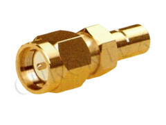
- SMA/MMCX: Compact in size, suitable for small devices such as mobile phones and wireless modules;
- BNC/RCA: Easy to plug and unplug, commonly used for temporary connections in video surveillance and test instruments;
- N-type/TNC: High weather resistance, suitable for harsh environments such as outdoor radars and base stations;
- F-type: Commonly used for cable TV connections in home TVs and set-top boxes;
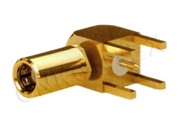
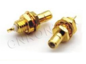
- SMC/SMB: Compact structure, suitable for space-constrained scenarios in automotive electronics and industrial control.
Each type is optimized for specific needs—for example, N-type connectors for outdoor use emphasize waterproof and dustproof performance, while MMCX for small devices pursues small size and high reliability.
III. Comprehensive Application: Ubiquitous from National Defense to Home Use
RF coaxial connectors are used in almost all high-frequency signal transmission scenarios. Typical scenarios include:
- National Defense and Industry: Signal links for vehicle rotating turrets, high-frequency transmission of radar antennas, command transmission of remote control systems;
- Civil Electronics: Image transmission in video surveillance systems (such as the connection between cameras and video recorders), high-frequency communication in transportation systems (such as signal transceiving for ETC);
- Consumer Field: Cable TV connections for home TVs, antenna docking of Bluetooth/Wi-Fi modules, audio signal transmission in sound systems (such as RCA connectors).
In simple terms, wherever inter-line connection of high-frequency signals is involved, RF coaxial connectors are present.
IV. Key Selection Factors: Matching Scenarios + System Compatibility
The core logic for selecting the right RF coaxial connector is scenario adaptation + system compatibility, which can be judged from 4 dimensions:
1. Interface Matching: First, Determine the Required Interface of the Device
Prioritize connectors that match the device's native interface (e.g., if the device interface is SMA, choose an SMA type) to avoid additional increases signal loss and may introduce interference.
2. Scenario Adaptation: The Environment Determines Which Type to Choose
- Outdoor/harsh environments: Choose N-type or TNC connectors with strong weather resistance;
- Space-constrained (e.g., mobile phones, modules): Choose small connectors such as SMA or MMCX;
- Temporary plugging (e.g., test instruments): Choose types that are easy to plug and unplug such as BNC or RCA.
3. System Compatibility: Parameters Need to Align
- Impedance matching: The characteristic impedance of the connector must be consistent with the system and cable (common 50Ω for industrial/national defense, 75Ω for civil video);
- Voltage and frequency: The operating voltage should not exceed the withstand voltage of the connector (to prevent breakdown), and the maximum operating frequency should cover the application scenario (e.g., 5G devices require connectors supporting 6GHz and above).
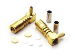
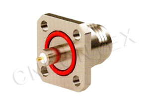
4. Installation and Termination: How to Connect? Choose the Corresponding Form
- Connecting cables: Choose cable termination connectors;
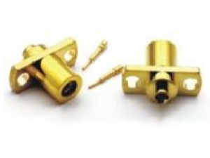
- Panel mounting: Choose panel mount type (fixed on the device casing);
- Connecting circuit boards: Choose PCB termination type (directly soldered to the circuit board).
V. Inspection Points: Ensure Usable and More Importantly Easy to Use
To avoid system failures caused by inferior connectors, inspection through mechanical + electrical dimensions is required:
1. Mechanical Performance: Check Durability
- Overall dimensions: Whether they meet design requirements (e.g., whether the interface pin position is accurate);
- Material and coating: Whether the metal shell is corrosion-resistant (e.g., stainless steel/gold plating), and whether plastic parts are high-temperature resistant;
- Insertion and extraction life: Whether the connection can be maintained after multiple insertions and extractions (generally required to be ≥500 times);
- Insertion and extraction force: Too loose and easy to fall off, too tight and easy to damage the device—moderate hand feel is sufficient.
2. Electrical Performance: Check Signal Transmission Capability
- Impedance matching: Use instruments to measure characteristic impedance to ensure consistency with the system (excessive deviation can easily cause signal reflection);
- Insulation and withstand voltage: Check whether it can withstand system voltage (e.g., connectors for industrial equipment need to withstand high voltage);
- Insertion loss: The smaller the loss, the better (generally required to be ≤0.3dB);
- Voltage Standing Wave Ratio (VSWR): The smaller the value (e.g., ≤1.2), the less signal reflection and the higher the transmission efficiency.
Conclusion: The Invisible Cornerstone of High-Frequency Systems
Although RF coaxial connectors are small, they are the invisible cornerstone of high-frequency systems—solving the core problem of how to stably connect high-frequency signals. From national defense radars to home TVs, from industrial control to consumer electronics, their presence makes high-frequency signals flow more stably and reliably.
Understanding their types, applications, and selection logic allows for precise selection in practical scenarios—after all, choosing the right connector adds a layer of stable guarantee to high-frequency systems.