What Are SMP and SSMP Connectors?
The
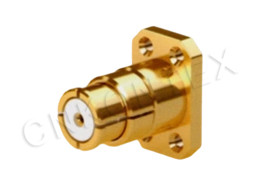
SMP (SubMiniature Push-on) connector is a blind-mate, push-on RF connector with a floating bullet contact, available in full-detent, limited-detent, and smooth-bore versions, with a frequency range typically rated to 40 GHz. SMP was developed by Gilbert (now Corning) and has become the dominant blind-mate interface for high-density RF modules.
The SSMP (SMPM, SubMiniature Push-on Miniature) connector is a smaller variant of SMP rated to 65 GHz in the same push-on blind-mate mechanical configuration, with body dimensions approximately 70% of SMP. SSMP follows the same IEC 61169-8 standard as SMP but extends the frequency range to 65 GHz and reduces the package size by ~30%.
Typical applications for SMP and SSMP:
5G massive-MIMO antenna arrays (board-to-board RF routing).
Phased-array radar modules (T/R module interconnects).
Microwave modules and hermetic packages.
Test fixtures (ATE) where multi-pin blind mating is required.
High-speed digital test fixtures (with RF extensions).
Satellite communication payloads.
The SMP/SSMP family's combination of small size, push-on mating, and high frequency makes it the dominant blind-mate interface for modern 5G and phased-array applications.
How Does the Blind-Mate Mechanism Work?
The SMP and SSMP connectors use a floating bullet (or "female-to-female adapter") that is captured inside the outer contact of one side and pushed into the receptacle of the other side during mating, with a limited axial and radial float to accommodate misalignment. The bullet is the replaceable wear element; the receptacles are mounted on the boards.
|
Mechanical feature |
Function |
|
Floating bullet |
Compensates for radial misalignment (typ. ±0.25 mm SMP, ±0.15 mm SSMP) |
|
Axial float |
Compensates for board-to-board gap variation (typ. ±0.25 mm SMP) |
|
Detent mechanism |
Holds bullet in place (full, limited, smooth) |
|
Hermetic option |
Glass-sealed receptacle for hermetic packages |
The blind-mate capability eliminates the need for precision fixturing when mating multiple RF channels simultaneously — a key requirement for 5G antenna arrays with 64, 128, or 256 elements.
What Are the Detent Options?
SMP and SSMP come in three detent versions, each providing a different combination of mating force, retention, and float. The detent determines the mechanical feel and the appropriate application.
|
Detent |
Mating force |
Retention |
Float |
Application |
|
Full detent (FD) |
~45 N |
~9 N |
Limited |
Highest vibration, smallest float |
|
Limited detent (LD) |
~22 N |
~4.5 N |
Moderate |
General-purpose blind mate |
|
Smooth bore (SB) |
~9 N |
~0.5 N |
Maximum |
Maximum float, test fixtures |
For production 5G antenna arrays, limited detent (LD) is the most common — it provides enough retention for shipping and handling while still allowing generous float for assembly tolerances.
What Are the Key Specifications?
The key SMP and SSMP specifications are frequency range, VSWR, insertion loss, axial float, radial float, and mating cycle durability. SMP and SSMP follow the IEC 61169-8 interface standard.
|
Specification |
SMP |
SSMP (SMPM) |
|
Frequency range |
DC – 40 GHz |
DC – 65 GHz |
|
VSWR (DC – 26.5 GHz) |
≤ 1.30 |
≤ 1.35 |
|
VSWR (26.5 – 40 GHz) |
≤ 1.45 |
n/a |
|
VSWR (40 – 65 GHz) |
n/a |
≤ 1.60 |
|
Insertion loss (DC – 40 GHz) |
≤ 0.40 dB |
n/a |
|
Insertion loss (DC – 65 GHz) |
n/a |
≤ 0.60 dB |
|
Axial float |
±0.25 mm |
±0.15 mm |
|
Radial float |
±0.25 mm |
±0.15 mm |
|
Mating cycles (FD) |
≥ 100 |
≥ 100 |
|
Mating cycles (LD) |
≥ 500 |
≥ 500 |
|
Mating cycles (SB) |
≥ 1000 |
≥ 1000 |
|
Impedance |
50 Ω |
50 Ω |
SSMP (SMPM) trades some mechanical float and mating durability for the smaller size and higher frequency range.
When Is SMP the Right Choice?
SMP is the right choice for high-density blind-mate RF interconnects up to 40 GHz in 5G antenna arrays, phased-array radar modules, and microwave modules where push-on blind mating with radial and axial float is required. SMP is the dominant blind-mate interface for 4G/5G base-station antenna arrays.
Decision factors:
Frequency. Up to 40 GHz (covers 5G FR1 and FR2 partially).
Mating. Push-on blind mate with floating bullet.
Float. ±0.25 mm radial and axial.
Density. High-density board-to-board layouts.
Detent. FD for vibration; LD for general; SB for test.
For 5G massive-MIMO 64T64R or 128T128R antenna arrays, SMP is the standard interface between the radio unit and the antenna panel, typically with 8–16 SMP channels per radio.
When Is SSMP (SMPM) the Right Choice?
SSMP (SMPM) is the right choice for blind-mate applications up to 65 GHz in 5G millimeter-wave modules, mm-wave radar (76–81 GHz automotive radar), and high-frequency test fixtures where the smaller form factor (70% of SMP) and higher frequency are required. SSMP is the emerging standard for 5G FR2 (24–40 GHz) and automotive radar modules.
Decision factors:
Frequency. Up to 65 GHz (covers 5G FR2, automotive radar).
Size. 70% of SMP body dimensions.
Float. ±0.15 mm (less than SMP but still generous).
Density. Highest-density mmWave layouts.
Detent. LD and SB are most common.
For 28 GHz, 39 GHz, and 60–90 GHz applications, SSMP is increasingly the interface of choice because it is the smallest push-on RF connector available with established tooling.
What Are the Mounting Styles?
SMP and SSMP receptacles are designed for surface-mount (SMT) or through-hole PCB mounting, with the receptacle soldered to the board and the floating bullet captured inside the SMT shroud. Compression-mount and solderless edge-mount versions are also available for specific applications.
|
Mounting style |
Description |
Application |
|
SMT receptacle |
Solder pads on PCB bottom |
Standard production |
|
Through-hole receptacle |
Pins through PCB |
Mechanical strength |
|
Compression-mount |
Pressure contact, no solder |
Test, prototyping |
|
Hermetic receptacle |
Glass-sealed pin |
Hermetic modules |
|
Cable-mount plug |
For external cable |
Test, system integration |
|
Adapter (SMP-to-SMA, etc.) |
Inter-series transition |
Test and instrumentation |
For 5G antenna arrays, SMT receptacles are standard, with the bullet captured inside a shroud on the opposite board or module. Kontex's SMP Series and SSMP Series include all standard mounting styles.
What Materials and Platings Are Used?
SMP and SSMP use stainless-steel or brass bodies with beryllium-copper center contacts and PTFE or PEEK insulators, with gold plating throughout the signal path for low loss and high durability. The floating bullet is typically beryllium copper with gold plating.
|
Component |
Material |
Plating |
|
Body |
Stainless steel (303 / 304) or brass |
Gold over nickel or passivated |
|
Center contact |
Beryllium copper (C17300) |
Gold over nickel |
|
Floating bullet |
Beryllium copper (C17300) |
Gold over nickel |
|
Insulator |
PTFE or PEEK |
n/a |
|
Detent spring |
Stainless steel or beryllium copper |
Gold over nickel |
|
Shroud |
Stainless steel or brass |
Gold over nickel |
The floating bullet is the wear element and is replaceable in higher-cycle applications.
How Does SMP Compare to Other Blind-Mate Interfaces?
SMP and SSMP sit between the larger, lower-frequency BMB and MMBX interfaces and the even smaller proprietary mmWave interfaces (P-SMP, Ganged SMP), with the dominant position in the 5G antenna array market. Kontex's 5G Board-to-Board family provides complementary solutions for higher-density 5G modules.
|
Interface |
Frequency |
Body size |
Float |
Mating force |
Application |
|
BMB |
18 GHz |
Large |
±0.5 mm |
High |
Legacy radar |
|
SMP |
40 GHz |
Medium |
±0.25 mm |
Medium |
5G, radar |
|
SSMP (SMPM) |
65 GHz |
Small |
±0.15 mm |
Medium |
mmWave, radar |
|
Ganged SMP |
40 GHz |
Medium |
±0.20 mm |
Medium |
Multi-channel arrays |
|
MMBX / MBX |
12 GHz |
Small |
±0.40 mm |
Low |
Board-to-board |
|
Ganged SSMP |
65 GHz |
Small |
±0.10 mm |
Low |
mmWave arrays |
For 5G mmWave (24–40 GHz) and automotive radar (76–81 GHz), SSMP is the standard blind-mate interface. For 5G FR1 (< 6 GHz) and macro/massive-MIMO, SMP remains the dominant interface.
What Are Common Applications in 5G?
SMP is the dominant blind-mate RF interface for 5G FR1 antenna arrays and base-station radios, while SSMP is the emerging standard for 5G FR2 (mmWave) modules. The combination supports the full 5G spectrum.
|
Application |
Frequency |
Connector |
Typical channels |
|
5G FR1 massive-MIMO (64T64R) |
3.5 GHz |
SMP |
8–16 per radio |
|
5G FR1 8T8R macro |
2.6 GHz |
SMP |
4–8 per radio |
|
5G FR2 mmWave module |
26–40 GHz |
SSMP |
4–8 per module |
|
5G small cell |
3.5–28 GHz |
SMP / SSMP |
2–4 |
|
Automotive radar |
76–81 GHz |
SSMP |
4–8 per radar |
Kontex's 5G Board-to-Board family provides complementary solutions for next-generation 5G modules that push beyond standard SMP/SSMP density.
What Are the Limitations?
SMP and SSMP have three main limitations: mating cycle durability (especially FD), float limitations that require careful board tolerance management, and limited power handling due to small center pin diameter. Each limitation is addressable.
|
Limitation |
Cause |
Mitigation |
|
Mating cycle limit |
Wear of bullet and detent |
Use LD or SB detent for higher cycles |
|
Float limit |
Tolerance on board, shroud |
Design within ±0.20 mm (SMP) |
|
Power limit |
Small center pin |
Use N-Type or 7/16 DIN for high power |
|
Frequency limit |
Resonant modes above 40/65 GHz |
Use 1.85 mm or 1.0 mm for > 65 GHz |
For production deployments, careful tolerance stack-up management is critical to ensure that all SMP/SSMP channels mate within the specified float envelope.
Frequently Asked Questions
Q: What is the difference between SMP and SSMP (SMPM)?
A: SMP is rated to 40 GHz and has the larger body. SSMP (also called SMPM, per IEC 61169-8) is rated to 65 GHz in a body approximately 70% the size of SMP. Both share the same basic push-on blind-mate mechanism with floating bullet.
Q: What is the difference between full detent, limited detent, and smooth bore?
A: Full detent (FD) has the highest mating force and retention (~9 N), used for high-vibration applications. Limited detent (LD) has moderate mating force and retention (~4.5 N), used for general blind mate. Smooth bore (SB) has the lowest mating force and retention (~0.5 N), used for test fixtures and maximum float.
Q: Can SMP and SSMP mate with each other?
A: No. SMP and SSMP are mechanically incompatible due to body size differences. An SMP-to-SSMP inter-series adapter is required for transitions.
Q: What is the typical mating cycle durability?
A: Full detent: ~100 cycles. Limited detent: ~500 cycles. Smooth bore: ~1000 cycles. The floating bullet is the wear element and is replaceable in some designs.
Q: What is the maximum frequency for SMP?
A: SMP is rated to 40 GHz per IEC 61169-8. For applications above 40 GHz (5G FR2 39 GHz, automotive radar), use SSMP (SMPM) to 65 GHz.
Q: Are SMP and SSMP available as cable assemblies?
A: Yes. Both are available as flexible and semi-rigid cable assemblies, typically with RG-405 (.085") or RG-402 (.141") semi-rigid for laboratory and test use.
Q: How is the floating bullet held in place during shipping?
A: The bullet is captured inside the shroud of one side (typically the "bullet" side or the "rail" side). For shipping, a protective cap is fitted over the shroud. The mating receptacle (on the board or module) is shipped without a bullet.
Q: Can SMP be used for power delivery?
A: SMP is designed for signal only and is limited to ~50 W CW at 1 GHz due to the small center pin. For higher power, use N-Type or 7/16 DIN.
Q: Does Kontex offer custom SMP/SSMP configurations?
A: Yes. Kontex offers custom SMP/SSMP configurations including ganged (multi-position) shrouds, custom PCB-launch geometries, and custom cable terminations. Contact the Kontex engineering team for custom requirements.
Conclusion
SMP and SSMP (SMPM) are the dominant blind-mate RF interfaces for high-density, high-frequency module interconnects, with SMP rated to 40 GHz for 5G FR1 antenna arrays and SSMP rated to 65 GHz for 5G FR2 mmWave and automotive radar modules. Kontex's SMP Series and SSMP Series provide standard and limited-detent versions with all mounting styles, complemented by the 5G Board-to-Board family for next-generation 5G modules. For product range, certifications, and engineering support, consult the Field Application and About pages.