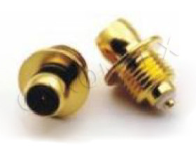
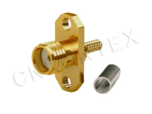
What Is an SMA Connector and Where Is It Used?
The
SMA (SubMiniature version A) connector is a coaxial RF connector with a 1/4"-36 UNS threaded coupling, 50 Ω characteristic impedance, and a frequency range typically rated to 18 GHz (18 GHz for the standard; up to 26.5 GHz for precision versions). SMA was developed in the 1960s as a smaller, higher-frequency alternative to the Type N and has become the most widely used RF connector for microwave applications.
Typical SMA applications:
Test and measurement equipment (network analyzers, spectrum analyzers).
Microwave components (amplifiers, filters, mixers, attenuators).
Antenna feeds for cellular, Wi-Fi, GPS, and radar.
RF modules for telecom base stations and backhaul.
Aerospace and defense electronics.
5G small cells and customer-premises equipment.
The SMA's combination of small size, threaded coupling (vibration-resistant), and good performance to 18 GHz has kept it as the default RF connector for more than 50 years.
What Are the Key SMA Specifications?
The key SMA specifications are impedance (50 Ω), frequency range, VSWR, insertion loss, contact resistance, dielectric withstanding voltage, and mating cycle durability. Each spec has a standard or typical value that defines the connector's performance envelope.
|
Specification |
Standard (MIL-STD-348 / IEC 60169) |
Typical premium value |
|
Characteristic impedance |
50 Ω |
50 Ω |
|
Frequency range (standard) |
DC – 18 GHz |
DC – 18 GHz |
|
Frequency range (precision) |
DC – 26.5 GHz |
DC – 26.5 GHz |
|
VSWR (DC – 18 GHz) |
≤ 1.30 |
≤ 1.10 |
|
Insertion loss (DC – 18 GHz) |
≤ 0.30 dB |
≤ 0.10 dB |
|
Contact resistance (center) |
≤ 3 mΩ |
≤ 1.5 mΩ |
|
Contact resistance (outer) |
≤ 2 mΩ |
≤ 1.0 mΩ |
|
Dielectric withstanding voltage |
1000 V RMS |
1500 V RMS |
|
Insulation resistance |
≥ 5000 MΩ |
≥ 5000 MΩ |
|
Mating cycles |
≥ 500 |
≥ 500 |
|
Coupling torque |
8 in-lbs (0.9 N·m) |
8 in-lbs (0.9 N·m) |
|
Temperature range |
−65 °C to +165 °C |
−65 °C to +165 °C |
The premium values are typical for precision stainless-steel SMA; standard brass SMA meets the MIL-STD values.
When Is SMA the Right Connector Choice?
SMA is the right choice when the application requires a threaded, vibration-resistant RF connector with 50 Ω impedance and a frequency range up to 18 GHz, in a compact form factor. SMA is the default for most microwave test and measurement, aerospace, and 5G applications.
Decision factors:
Frequency. Up to 18 GHz (standard) or 26.5 GHz (precision).
Coupling. Threaded for vibration resistance (vs. push-on or bayonet).
Impedance. 50 Ω (SMA is not available in 75 Ω).
Power. Up to ~200 W CW at 1 GHz; lower at higher frequencies.
Size. Compact for dense packaging; sub-miniature alternatives for higher density.
Cost. Standard brass SMA is economical; precision stainless steel is premium.
For applications above 26.5 GHz, the 2.92 mm or 2.4 mm connector families are preferred. For applications below 1 GHz with a 75 Ω impedance, the BNC or F-type connector is preferred. For high-density board-to-board, the SMP or 5G BTB connector is preferred.
How Are Gender and Polarity Defined?
SMA gender follows the convention that the plug (male) has the center pin and the jack (female) has the center socket — and the threaded coupling nut determines the outer contact. Reverse-polarity SMA (RP-SMA) exists but is not standard for microwave applications.
|
Configuration |
Center contact |
Outer contact |
Coupling |
|
SMA plug (male) |
Pin |
Socket (inside the coupling nut) |
Outer threaded nut |
|
SMA jack (female) |
Socket |
Pin (threaded post) |
Threads on body |
Standard SMA cable assemblies have a plug on one end and a jack on the other. PCB-mount SMA is typically a jack with a vertical or right-angle through-hole or surface-mount pin. Bulkhead SMA is typically a jack with a threaded body for panel mounting and a nut for fixing.
What Mounting Styles Are Available?
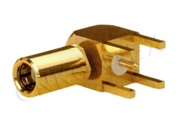
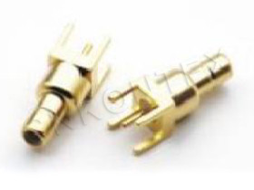
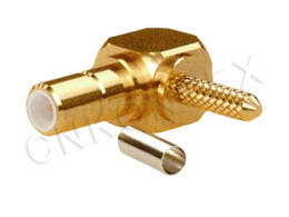
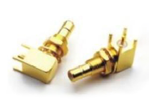
SMA connectors are available in cable-mount, panel-mount (bulkhead), PCB-mount, and in-line (adapter) styles, with the choice determined by the application's mechanical and electrical requirements. Kontex's SMA Series covers all standard mounting styles.
|
Mounting style |
Typical use |
Body configuration |
|
Cable straight plug |
Cable-end termination |
Hex or knurled coupling nut |
|
Cable right-angle plug |
Cable-end termination, tight spaces |
Right-angle body |
|
Cable bulkhead jack |
Panel feed-through for cable |
Threaded body + panel nut |
|
PCB vertical jack |
PCB launch, vertical mount |
Through-hole or SMT pin |
|
PCB right-angle jack |
PCB launch, parallel to board |
Right-angle pin |
|
Panel-mount jack |
Panel feed-through, no cable |
4-hole or 2-hole flange |
|
In-line adapter |
Two jack-to-jack or plug-to-plug |
Barrel body |
PCB-mount SMA requires careful attention to the launch geometry (transmission-line width, ground plane clearance, via fence) to maintain 50 Ω impedance through the board transition.
What Materials and Platings Are Used?
SMA connectors are typically made from brass (standard) or stainless steel (precision), with the center contact made from beryllium copper or brass, and the insulator from PTFE or PEEK. Plating is gold over nickel for the contacts; passivated stainless steel or nickel-plated brass for the body.
|
Component |
Standard material |
Precision material |
Standard plating |
|
Body |
Brass (C36000) |
Stainless steel (303 / 304) |
Gold over nickel or passivated |
|
Center contact |
Beryllium copper (C17300) |
Beryllium copper (C17300) |
Gold over nickel |
|
Outer contact |
Brass or beryllium copper |
Stainless steel |
Gold over nickel |
|
Insulator |
PTFE |
PTFE |
n/a |
|
Coupling nut |
Brass |
Stainless steel |
Gold over nickel or passivated |
|
Gasket / O-ring |
Silicone rubber |
Silicone rubber |
n/a |
Plating selection is a trade-off: gold over nickel provides the best electrical performance and corrosion resistance; passivated stainless steel provides better mechanical durability. The article RF Connector Plating: Gold vs Silver vs Nickel covers this in detail.
What Are the Standard Cable Compatibility Groups?
SMA connectors are designed for flexible coaxial cables in the 0.085" to 0.250" OD range, with the specific cable group depending on the connector's cable-entry design. Common cable groups include RG-58, RG-174, RG-178, RG-316, RG-400, LMR-100, LMR-200, LMR-240, LMR-400, and semi-rigid alternatives.
|
Cable group |
OD (in) |
Impedance |
Frequency limit |
Typical use |
|
RG-178 |
0.072 |
50 Ω |
3 GHz |
Low-power, flexible |
|
RG-174 / RG-316 |
0.110 |
50 Ω |
3 GHz |
Low-power, flexible |
|
RG-58 |
0.195 |
50 Ω |
5 GHz |
General-purpose |
|
RG-400 |
0.195 |
50 Ω |
12 GHz |
High-temperature, flexible |
|
LMR-200 |
0.195 |
50 Ω |
6 GHz |
Low-loss, flexible |
|
LMR-240 |
0.240 |
50 Ω |
6 GHz |
Low-loss, flexible |
|
LMR-400 |
0.405 |
50 Ω |
6 GHz |
Low-loss, higher power |
|
RG-405 (.085 semi-rigid) |
0.085 |
50 Ω |
40 GHz |
Precision, lab |
|
RG-402 (.141 semi-rigid) |
0.141 |
50 Ω |
34 GHz |
Precision, lab |
Cables above 18 GHz (semi-rigid RG-405, RG-402) require precision SMA with tighter tolerances for stable VSWR.
What Are VSWR and Insertion Loss Targets?
VSWR (voltage standing wave ratio) and insertion loss are the two key RF performance metrics for SMA connectors, with premium targets of ≤ 1.10 VSWR and ≤ 0.10 dB insertion loss to 18 GHz. The standard targets are ≤ 1.30 VSWR and ≤ 0.30 dB.
|
Frequency |
Standard VSWR |
Premium VSWR |
Insertion loss |
|
DC – 6 GHz |
≤ 1.15 |
≤ 1.05 |
≤ 0.10 dB |
|
6 – 12 GHz |
≤ 1.20 |
≤ 1.10 |
≤ 0.20 dB |
|
12 – 18 GHz |
≤ 1.30 |
≤ 1.15 |
≤ 0.30 dB |
|
18 – 26.5 GHz (precision) |
≤ 1.35 |
≤ 1.20 |
≤ 0.40 dB |
Lower VSWR and lower insertion loss are achieved by tighter mechanical tolerances (especially on the center contact and the dielectric), by precision machining, and by gold plating on the contacts.
How Is SMA Torqued?
SMA connectors are torqued to 8 in-lbs (0.9 N·m) using a calibrated torque wrench, with the standard procedure being to hold the mating connector stationary and rotate only the coupling nut. Over-torque damages the contact, under-torque causes poor VSWR and intermittent connections.
|
Torque value |
Application |
|
8 in-lbs (0.9 N·m) |
Standard SMA (per MIL-STD-348) |
|
5 in-lbs (0.56 N·m) |
Precision SMA with polymer bead |
|
12 in-lbs (1.35 N·m) |
TNC (heavier thread) |
For mating a male-female pair, hold the female connector's body stationary with a wrench and rotate the male coupling nut to the specified torque. For mating with a torque wrench, use a "break-over" torque wrench that prevents over-torque.
What Are the SMA Limitations?
SMA has four main limitations: frequency ceiling at 18–26.5 GHz, fragility of the polymer bead inside the jack, no 75 Ω variant, and limited power handling above 10 GHz. Each limitation has a known workaround or alternative connector family.
|
Limitation |
Cause |
Workaround / alternative |
|
Frequency ceiling |
Resonant modes in the center contact |
Use 2.92 mm, 2.4 mm, or 1.85 mm above 26.5 GHz |
|
Fragile polymer bead |
Bead is required for center contact support in some designs |
Use precision SMA with air dielectric |
|
No 75 Ω variant |
Standard is 50 Ω only |
Use BNC or F-type for 75 Ω |
|
Power limit |
Small center pin diameter |
Use N-type or 7/16 DIN for higher power |
|
Mating cycle limit |
Wear of the polymer bead |
Replace after 500 cycles; use ruggedized SMA |
How Does SMA Compare to Other Connector Families?
SMA sits between BNC/TNC (lower frequency, less precise) and 2.92 mm / 2.4 mm (higher frequency, more precise) in the RF connector hierarchy, with threaded coupling and 50 Ω impedance as its defining features. The comparison is based on frequency range, coupling mechanism, and size.
|
Connector |
Frequency |
Coupling |
Impedance |
Body size |
|
BNC |
4 GHz |
Bayonet |
50 Ω / 75 Ω |
Medium |
|
TNC |
11 GHz |
Threaded |
50 Ω / 75 Ω |
Medium |
|
N |
11 GHz |
Threaded |
50 Ω / 75 Ω |
Large |
|
SMA |
18 GHz |
Threaded |
50 Ω |
Small |
|
2.92 mm |
40 GHz |
Threaded |
50 Ω |
Small |
|
2.4 mm |
50 GHz |
Threaded |
50 Ω |
Very small |
|
7/16 DIN (L29) |
7.5 GHz |
Threaded |
50 Ω |
Very large |
|
FAKRA |
6 GHz |
Snap |
50 Ω |
Small |
For applications in the 18–40 GHz range, Kontex's 2.92 mm series provides a compatible mechanical upgrade from SMA (the 2.92 mm was designed to mate with SMA and 3.5 mm connectors).
Frequently Asked Questions
Q: What is the difference between SMA and 3.5 mm connectors?
A: SMA and 3.5 mm have the same mechanical coupling, but 3.5 mm uses an air dielectric (no polymer bead) for higher frequency operation and better repeatability. 3.5 mm is rated to 34 GHz vs SMA's 18 GHz.
Q: Can SMA be used above 18 GHz?
A: Standard SMA is rated to 18 GHz but will physically operate to higher frequencies with degraded VSWR. Precision SMA with air dielectric is rated to 26.5 GHz. Above 26.5 GHz, use 2.92 mm or 2.4 mm.
Q: What is the maximum power SMA can handle?
A: SMA can handle approximately 200 W CW at 1 GHz, decreasing with frequency to about 50 W CW at 18 GHz. The peak power limit (for pulsed applications) is approximately 1 kW.
Q: What is RP-SMA?
A: RP-SMA (Reverse-Polarity SMA) is a non-standard variant where the plug has the center socket and the jack has the center pin. RP-SMA was popularized for Wi-Fi equipment but is not recommended for professional microwave applications.
Q: Can SMA and 2.92 mm be mated together?
A: Yes, but with care. The 2.92 mm was designed to mechanically mate with SMA and 3.5 mm. The 2.92 mm's air dielectric may be damaged if mated repeatedly with an SMA that has a protruding polymer bead.
Q: How many mating cycles can an SMA connector sustain?
A: Standard SMA is rated for 500 mating cycles. Precision SMA with air dielectric can sustain 1000–5000 cycles. The mating cycle count is the dominant wear mechanism; connector life is essentially the life of the polymer bead.
Q: What torque is required for SMA?
A: 8 in-lbs (0.9 N·m) per MIL-STD-348. Use a calibrated torque wrench to avoid over-torque, which damages the polymer bead.
Q: What is the best cable for SMA at 18 GHz?
A: For 18 GHz operation, use RG-405 (0.085" semi-rigid) or RG-402 (0.141" semi-rigid) with precision SMA. Flexible cables (LMR-240, LMR-400) are limited to 6 GHz.
Q: Does Kontex offer custom SMA connectors?
A: Yes. Kontex offers custom SMA configurations including non-standard cable groups, custom flange patterns, and special plating. Contact the Kontex engineering team for custom requirements.
Conclusion
SMA is the default RF connector for microwave applications up to 18 GHz, with the right selection driven by frequency range, gender, mounting style, body material, plating, and cable compatibility. Kontex's SMA Series covers the full range from standard 18 GHz brass to precision stainless-steel versions, with the SSMA Series for miniaturized applications and the RF Adapter Series for inter-series transitions. Pair the connector selection with the appropriate RF Cable Assembly and consult the Field Application and About pages for company capability and export documentation.