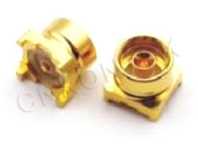
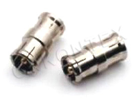
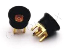
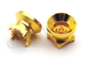
What Is an RF Cable Assembly?
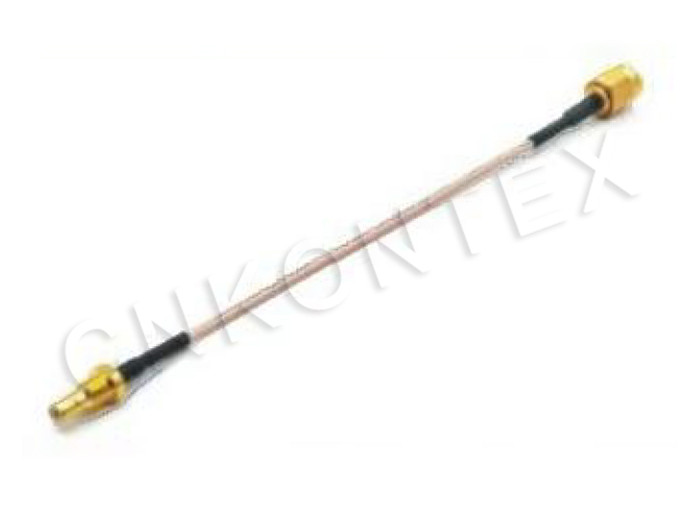
An RF cable assembly is a finished coaxial cable product with connectors pre-attached to one or both ends, designed and tested as a complete electrical and mechanical assembly rather than as separate components. RF cable assemblies combine cable selection (RG, LMR, semi-rigid, corrugated), connector selection (SMA, N-Type, 7/16 DIN, FAKRA, etc.), termination process (crimp, solder, clamp), and post-assembly testing (VSWR, insertion loss, PIM).
Typical RF cable assembly applications:
Test and measurement cables (lab and production).
Base-station jumper cables (cellular, broadcast).
Radar and avionics interconnect.
Vehicle wiring harnesses (FAKRA, HSD).
5G small-cell and macro-cell feeders.
Medical imaging (MRI coils, RF ablation).
Industrial RF (heating, plasma generation).
A cable assembly is more than the sum of its parts because the termination process — how the connector is attached to the cable — determines the assembly's overall electrical performance, mechanical durability, and PIM.
What Are the Main Cable Types?
RF cable assemblies use a range of coaxial cable types, from low-cost flexible RG series to low-loss LMR, precision semi-rigid, and high-power corrugated base-station cables. Each cable type has a different electrical, mechanical, and cost profile.
|
Cable family |
Construction |
Frequency limit |
Loss (typ. per m @ 1 GHz) |
Flex |
Cost |
|
RG-58 / RG-174 |
Stranded center, foil + braid |
3–5 GHz |
0.6–1.0 dB/m |
High |
Low |
|
RG-316 / RG-400 |
Stranded center, braid |
3–12 GHz |
0.4–0.7 dB/m |
High |
Low–medium |
|
LMR-100 / LMR-200 |
Solid center, foil + braid |
6 GHz |
0.4–0.7 dB/m |
Medium |
Low |
|
LMR-240 / LMR-400 |
Solid center, foil + braid |
6 GHz |
0.2–0.4 dB/m |
Medium |
Medium |
|
LMR-600 / LMR-900 |
Solid center, foil + braid |
6 GHz |
0.1–0.2 dB/m |
Low |
Medium–high |
|
Semi-rigid RG-405 (.085) |
Solid center, solid copper jacket |
40 GHz |
0.5 dB/m @ 10 GHz |
None |
High |
|
Semi-rigid RG-402 (.141) |
Solid center, solid copper jacket |
34 GHz |
0.3 dB/m @ 10 GHz |
None |
High |
|
Hand-formable .085 / .141 |
Tin-plated copper braid over dielectric |
18–40 GHz |
0.5–0.7 dB/m @ 10 GHz |
Limited |
Medium |
|
Corrugated 1/2" |
Foam dielectric, corrugated outer |
6 GHz |
0.05 dB/m |
None |
High |
|
Corrugated 7/8" |
Foam dielectric, corrugated outer |
5 GHz |
0.03 dB/m |
None |
High |
For laboratory and test, semi-rigid and hand-formable dominate. For flexible test and measurement, RG/LMR are standard. For base-station feeders, corrugated 1/2" to 1-5/8" cables dominate.
What Connectors Are Used?
RF cable assemblies use connector families that match the cable impedance and the application's mechanical and electrical requirements, with the most common being SMA, N-Type, BNC, TNC, 7/16 DIN, and FAKRA.
|
Connector family |
Impedance |
Frequency |
Typical cables |
Application |
|
SMA |
50 Ω |
18 GHz |
RG-174, RG-316, LMR-100/200, .085 semi-rigid |
Test, microwave |
|
N-Type |
50 Ω / 75 Ω |
11 GHz |
RG-58, RG-213, LMR-400 |
Base-station, instrumentation |
|
BNC |
50 Ω / 75 Ω |
4 GHz |
RG-58, RG-174, RG-178 |
Test, video |
|
TNC |
50 Ω |
11 GHz |
RG-58, LMR-200 |
Test, threaded coupling |
|
7/16 DIN (L29) |
50 Ω |
7.5 GHz |
1/2", 7/8" corrugated |
Base-station feeders |
|
FAKRA |
50 Ω / 75 Ω |
6 GHz |
RTK 031, RTK 047 |
Automotive |
|
MCX / MMCX |
50 Ω |
6 GHz |
RG-174, RG-316 |
Compact consumer |
|
SMB |
50 Ω |
4 GHz |
RG-174, RG-316 |
Industrial, automotive |
|
2.92 mm |
50 Ω |
40 GHz |
.085 semi-rigid, RG-405 |
mmWave, 5G |
Kontex's RF Cable Assembly Series provides pre-terminated assemblies with all standard connector families and cable types.
What Are the Termination Methods?
RF cable assembly termination methods include crimp, solder, clamp, and weld, with each method providing a different balance of electrical performance, mechanical strength, and field-serviceability. The termination method affects VSWR, PIM, and mechanical life.
|
Method |
Process |
Advantages |
Disadvantages |
|
Crimp |
Mechanical compression of ferrule |
Fast, field-repairable, consistent |
Requires calibrated crimp tool |
|
Solder |
Solder center pin to cable |
Excellent electrical, low cost |
Requires skilled operator, not field-repairable |
|
Clamp |
Mechanical clamp body |
Field-repairable, no special tools |
Bulkier, less consistent |
|
Weld (laser / resistance) |
Fusion of ferrule |
Highest mechanical strength, hermetic |
Requires specialized equipment |
|
Solderless (compression) |
Spring contact |
Quick, field-repairable |
Highest VSWR, limited frequency
|
For low-PIM base-station applications (7/16 DIN, LTE/5G), crimp with calibrated tooling is standard. For laboratory semi-rigid cables (RG-405, RG-402), solder is standard. For high-reliability aerospace, laser welding is used.
How Is the Center Pin Attached?
The center pin attachment is the most critical termination step, because any gap, off-center pin, or incomplete solder joint causes VSWR spike, insertion loss, and PIM. Three methods dominate.
|
Pin attachment |
Process |
Application |
|
Solder |
Center pin soldered to cable center conductor |
Semi-rigid, hand-formable, RG/LMR |
|
Crimp |
Center pin crimped to cable center conductor |
Crimp-style flexible cables |
|
Spring / set screw |
Center pin held by spring tension |
Solderless / field-repairable |
For SMA and 2.92 mm precision assemblies, solder is the standard because it provides the lowest VSWR and the most consistent contact. For crimp-style flexible cables (RG/LMR with crimp connectors), calibrated crimp tooling is required.
What About Strain Relief and Bending?
Strain relief and minimum bend radius are critical for RF cable assembly durability, with excessive bending causing center conductor migration, dielectric cracking, and eventual failure. Each cable type has a specified minimum bend radius.
|
Cable family |
Min bend radius (static) |
Min bend radius (dynamic) |
Notes |
|
RG-174 |
10 mm |
20 mm |
High flex |
|
RG-316 |
10 mm |
25 mm |
High flex |
|
LMR-100 |
6 mm |
25 mm |
Low flex |
|
LMR-200 |
12 mm |
25 mm |
Low flex |
|
LMR-240 |
19 mm |
50 mm |
Medium flex |
|
LMR-400 |
25 mm |
100 mm |
Low flex |
|
.085 semi-rigid |
6 mm |
n/a |
No flex |
|
.141 semi-rigid |
8 mm |
n/a |
No flex |
|
1/2" corrugated |
70 mm |
200 mm |
No flex |
For dynamic flexing applications (cable flexed repeatedly during operation), the minimum bend radius for dynamic flexing is typically 2× the static minimum. Cable assemblies with strain relief boots and bend-limiting sleeves are required for applications with vibration or repeated movement.
How Is VSWR Measured?
VSWR (Voltage Standing Wave Ratio) and insertion loss are measured with a vector network analyzer (VNA) using a calibrated test setup, with the cable assembly measured end-to-end through calibrated connectors. The test confirms that the assembly meets the specified electrical performance.
|
Test |
Equipment |
Typical limit |
|
VSWR (return loss) |
VNA, calibrated |
≤ 1.30 (typ. precision: ≤ 1.20) |
|
Insertion loss |
VNA, calibrated |
Per cable spec (e.g., LMR-400: 0.2 dB/m @ 1 GHz) |
|
PIM |
PIM analyzer, 2 × 43 dBm |
≤ −155 dBc (LTE/5G), ≤ −130 dBc (general) |
|
Continuity / shorts |
DMM |
n/a |
|
Hi-pot / dielectric withstanding |
Hi-pot tester |
1000 V RMS |
|
Phase matching |
VNA with phase reference |
±2° or ±5° for phased arrays |
For phased-array applications (5G massive-MIMO, radar), phase matching between cable assemblies within a single array is critical. Cable assemblies are typically phase-matched to within ±2° or ±5° at the operating frequency.
What Are the Standard Tests?
Beyond VSWR and insertion loss, RF cable assemblies undergo mechanical, environmental, and durability tests to verify production quality and long-term reliability.
|
Test |
Standard |
Method |
|
Mating cycle durability |
IEC 61169 |
500 (typ.) or 1000 (precision) mate cycles |
|
Flex life |
Manufacturer spec |
Bend to min radius, count to failure |
|
Pull-off force |
IEC 61169 |
Apply axial pull to connector, measure force |
|
Torque |
IEC 61169 |
Apply torque to coupling nut |
|
Vibration |
IEC 60068-2-6 |
Sweep frequency, measure electrical stability |
|
Thermal shock |
IEC 60068-2-14 |
−40 °C to +85 °C, measure VSWR |
|
Humidity |
IEC 60068-2-78 |
95 % RH, 96 h, measure VSWR |
|
Salt spray |
IEC 60068-2-52 |
Marine environment, measure corrosion |
For military and aerospace, the full IEC 60068 environmental test suite is standard.
How Is Phase and Amplitude Stability Achieved?
Phase stability and amplitude stability under flex are critical for phased-array radar and 5G beamforming applications, requiring cable assemblies with minimal electrical change under mechanical flex. Semi-rigid and corrugated cables provide the best stability.
|
Cable family |
Phase stability (typ. per flex cycle @ 6 GHz) |
Amplitude stability |
|
RG-174 / RG-316 |
±10° |
±0.5 dB |
|
LMR-200 / LMR-240 |
±5° |
±0.3 dB |
|
LMR-400 / LMR-600 |
±3° |
±0.2 dB |
|
.085 / .141 semi-rigid |
n/a (no flex) |
n/a |
|
Corrugated 1/2" / 7/8" |
±1° |
±0.1 dB |
For test-and-measurement cables (phase-stable coax), specialized constructions minimize phase change under flex. These cables are premium products but are required for vector network analyzer test port extensions and production ATE.
What About Custom Lengths and Phase Matching?
Custom-length and phase-matched cable assemblies are common for phased-array radar, 5G massive-MIMO, and ATE applications, where cables within a single system must have matched electrical length to within ±2° or ±5°.
|
Application |
Phase match requirement |
Typical tolerance |
|
5G massive-MIMO array |
≤ ±2° @ 3.5 GHz |
±5 mm cable length |
|
Phased-array radar |
≤ ±5° @ 10 GHz |
±2 mm cable length |
|
ATE test fixture |
≤ ±1° @ 6 GHz |
±1 mm cable length |
|
MIMO test (4 channels) |
≤ ±1° @ 6 GHz |
±1 mm cable length |
Kontex's RF Cable Assembly Series provides custom-length and phase-matched assemblies with documented test reports.
Frequently Asked Questions
Q: What is the difference between an RG cable and an LMR cable?
A: RG cables are general-purpose coax with stranded center conductor and moderate shielding, used for low-frequency (< 3 GHz) applications. LMR cables are engineered for lower loss (foil + braid shielding, solid center conductor, better dielectric) and are used for 6 GHz and long-run applications.
Q: What is the best cable for a 6 GHz test setup?
A: For 6 GHz test, use LMR-240 (flexible) for general purpose or LMR-400 (flexible, lower loss) for longer runs. For 6 GHz with phase stability, use semi-rigid .141 with precision SMA or N-Type connectors.
Q: Can I make my own RF cable assemblies?
A: Yes for low-frequency (< 3 GHz) flexible cables with crimp connectors. For high-frequency, low-PIM, or phase-stable assemblies, factory termination is recommended because of the precision required for consistent VSWR and PIM.
Q: What is the typical lead time for a custom cable assembly?
A: Stock flexible assemblies ship in 1–2 weeks. Custom-length or phase-matched assemblies typically ship in 2–4 weeks depending on complexity and testing requirements.
Q: What is PIM and why is it important?
A: PIM (Passive Intermodulation) is the generation of unwanted intermodulation products at connector interfaces, typically due to nonlinearities in metal-to-metal contact, ferromagnetic materials, or loose mechanical coupling. PIM is critical for LTE/5G base stations because intermodulation products fall into the receive band and degrade SINR.
Q: Can RG-58 cable be used above 5 GHz?
A: RG-58 is rated to 5 GHz but with rapidly increasing loss and poor shielding effectiveness. For applications above 5 GHz, use LMR-240, LMR-400, or semi-rigid coax.
Q: What is the difference between crimp and solder termination?
A: Crimp termination uses a calibrated crimp tool to mechanically compress a ferrule onto the cable, providing fast, field-repairable connections. Solder termination uses solder to attach the center pin and shell, providing the lowest VSWR but requiring a skilled operator and not field-repairable.
Q: Does Kontex offer custom cable assemblies?
A: Yes. Kontex's Cable Assembly page covers custom configurations including custom lengths, phase matching, special cable groups, and pre-terminated harnesses for OEM integration. Contact the Kontex engineering team for custom requirements.
Conclusion
An RF cable assembly is a precisely engineered combination of cable, connectors, termination process, and testing, where each element determines the assembly's electrical and mechanical performance. Proper selection requires matching cable type to frequency and environment, connector family to cable and application, and termination method to performance and field-serviceability requirements. Kontex's RF Cable Assembly Series and Cable Assembly provide the full range from stock flexible to custom phase-matched assemblies, terminated with connectors from the SMA Series through 7/16 DIN (L29) and FAKRA families. For product range, certifications, and engineering support, consult the Field Application and About pages.