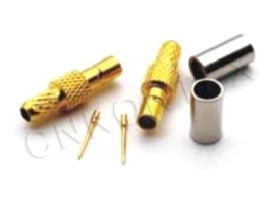
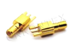
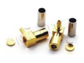
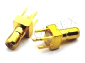
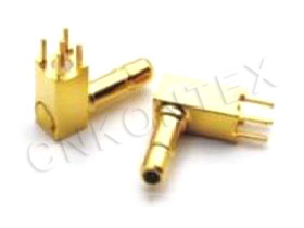
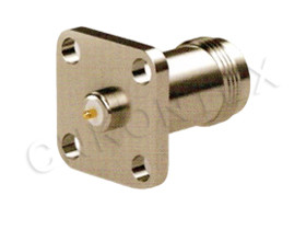
Why Is Precision Machining Critical for RF Connectors?
RF connectors require precision machining because the electrical performance (VSWR, insertion loss, PIM) is directly determined by the mechanical accuracy of the center conductor geometry, dielectric support, and outer conductor concentricity, with typical critical tolerances of ±0.01 mm at frequencies above 18 GHz. A 0.05 mm lateral offset of the center pin can degrade VSWR from ≤ 1.10 to ≥ 1.30 at 18 GHz.
Key precision-machining requirements:
Center conductor concentricity to outer conductor: ±0.02 mm (typ.).
Surface finish on mating surfaces: Ra ≤ 0.4 μm (typ.).
Critical diameter tolerances: ±0.01 to ±0.03 mm.
Thread accuracy: Class 2A/2B (UNS) or 6g/6H (metric).
Plating thickness control: ±20 % of nominal.
These tolerances are beyond the capability of standard CNC turning/milling and require dedicated precision machining centers with in-process measurement.
What Materials Are Used?
RF connector bodies are typically machined from brass (C36000) for general-purpose connectors or stainless steel (303/304) for precision and rugged applications, with beryllium copper (C17300) used for the center contact and PTFE or PEEK used for the dielectric insulator. The choice of material affects machinability, plating performance, and mechanical durability.
|
Component |
Standard material |
Precision material |
Notes |
|
Body |
Brass (C36000) |
Stainless steel (303 / 304) |
Brass for general; SS for rugged, precision |
|
Center contact |
Beryllium copper (C17300) |
Beryllium copper (C17300) |
Spring + conductivity |
|
Outer contact |
Brass |
Stainless steel |
Matched to body |
|
Insulator |
PTFE |
PTFE or PEEK |
Low-loss, stable dielectric |
|
Coupling nut |
Brass |
Stainless steel |
Matched to body |
|
Gasket / O-ring |
Silicone rubber |
Silicone rubber |
IP sealing |
Brass C36000 is the standard because it is free-machining (high lead content for chip breaking), has good electrical conductivity, and accepts gold or silver plating readily. Stainless steel 303 is the standard for precision connectors because of its dimensional stability and corrosion resistance.
What Are the Critical Machining Tolerances?
The critical RF connector body machining tolerances are ±0.01–0.03 mm on center conductor and outer conductor diameters, ±0.02 mm on concentricity, and Ra ≤ 0.4 μm on mating surfaces, with less critical features (body OD, knurl, mounting holes) toleranced at ±0.05 mm. The tolerance depends on the connector family and frequency range.
|
Feature |
Standard tolerance |
Precision tolerance |
Notes |
|
Center conductor OD |
±0.02 mm |
±0.01 mm |
Affects Z₀ |
|
Outer conductor ID |
±0.02 mm |
±0.01 mm |
Affects Z₀ |
|
Center-to-outer concentricity |
±0.05 mm |
±0.02 mm |
Affects VSWR |
|
Mating surface finish |
Ra ≤ 0.8 μm |
Ra ≤ 0.4 μm |
Affects contact resistance |
|
Thread accuracy |
Class 2A |
Class 1A |
Affects mating force |
|
Critical length |
±0.05 mm |
±0.02 mm |
Affects electrical length |
|
Non-critical OD |
±0.10 mm |
±0.05 mm |
Cosmetic |
For 18 GHz SMA, the standard tolerance of ±0.02 mm provides VSWR ≤ 1.30. For precision 26.5 GHz SMA, the precision tolerance of ±0.01 mm provides VSWR ≤ 1.20.
What CNC Processes Are Used?
RF connector body machining uses precision CNC turning (for cylindrical features) and CNC milling (for flats, mounting features, and complex geometry), with secondary operations including drilling, tapping, deburring, and inspection. Each operation requires specific tooling and fixturing.
|
Operation |
Machine |
Typical tolerance |
Notes |
|
CNC turning |
Swiss-type or lathe |
±0.005 mm |
Cylindrical features, threads |
|
CNC milling |
3-axis VMC |
±0.01 mm |
Flats, slots, mounting features |
|
CNC drilling |
VMC or lathe |
±0.02 mm |
Center pin hole, mounting holes |
|
Tapping |
Lathe or VMC |
Class 2A |
Threads |
|
Deburring |
Manual or vibratory |
n/a |
Edge preparation |
|
Inspection |
CMM or optical |
±0.001 mm |
Critical dimensions |
For high-volume production, Swiss-type lathes with integrated milling spindles are the standard for RF connector bodies because they allow complete machining in a single setup with high precision and short cycle times.
What Is the Machining Workflow?
A typical RF connector body machining workflow includes material preparation, CNC turning of the OD and ID features, CNC milling of flats and mounting features, drilling, tapping, deburring, cleaning, inspection, and plating. Each step requires specific quality control.
|
Step |
Description |
Quality check |
|
1. Material |
Cut bar stock to length |
Material cert |
|
2. CNC turning |
Machine OD, ID, threads |
In-process diameter check |
|
3. CNC milling |
Flats, slots, mounting features |
Visual + dimensional |
|
4. Drilling |
Center pin hole, mounting holes |
Hole diameter, depth |
|
5. Tapping |
Internal threads |
Thread gauge |
|
6. Deburring |
Remove sharp edges |
Visual |
|
7. Cleaning |
Remove coolant, chips |
Visual + cleanliness test |
|
8. Inspection |
Critical dimensions |
CMM or optical |
|
9. Plating |
Au, Ag, Ni, tri-metal |
Plating thickness (XRF) |
|
10. Final inspection |
Electrical + mechanical |
VSWR sample test |
For precision connectors, 100 % in-process inspection of critical dimensions is standard, with periodic electrical testing on production samples.
What Is Surface Finish and Why Does It Matter?
Surface finish on RF connector mating surfaces is critical because the RF current flows at the surface (skin effect), and rough surfaces increase contact resistance and reduce mating cycle durability. The standard finish for RF mating surfaces is Ra ≤ 0.4 μm (16 μin).
|
Surface finish |
Application |
Notes |
|
Ra ≤ 0.4 μm |
Mating surfaces, signal contact |
Standard for SMA, N-Type, etc. |
|
Ra ≤ 0.8 μm |
Outer body, non-critical |
Standard for general features |
|
Ra ≤ 1.6 μm |
Knurl, body OD |
Cosmetic, hand-hold |
|
Ra ≤ 0.1 μm |
Precision mmWave, 1.85 mm |
Premium |
For mmWave connectors (1.85 mm, 1.0 mm), surface finish Ra ≤ 0.1 μm (4 μin) is required to maintain VSWR ≤ 1.30 at 65 GHz.
How Is Concentricity Controlled?
Concentricity between the center conductor and the outer conductor is controlled by machining both features in a single setup on a precision lathe, with the part never released from the spindle until all critical features are complete. Releasing and re-chucking the part introduces runout that degrades concentricity.
|
Method |
Concentricity achievable |
Notes |
|
Single-setup turning |
±0.01 mm |
Best, requires Swiss-type or 5-axis lathe |
|
Two-setup turning with collet |
±0.02 mm |
Good for standard |
|
Turning + secondary mill |
±0.05 mm |
Adequate for low-frequency |
|
Separate center pin assembly |
±0.10 mm |
Acceptable for power connectors |
For precision SMA at 26.5 GHz, single-setup turning with in-process measurement is standard.
What Is Plating Control?
Plating thickness and uniformity must be controlled to ±20 % of nominal to ensure consistent VSWR and mating cycle performance, with plating typically applied by electroplating (for gold, silver, nickel) or electroless plating (for nickel-P). Plating thickness is verified by X-ray fluorescence (XRF) on production samples.
|
Plating |
Thickness (typ.) |
Thickness tolerance |
Verification |
|
Gold |
30 μin (0.75 μm) |
±20 % |
XRF |
|
Silver |
200 μin (5 μm) |
±20 % |
XRF |
|
Nickel |
200 μin (5 μm) |
±20 % |
XRF |
|
Tri-metal |
200 μin (5 μm) |
±25 % |
XRF |
For low-PIM applications, plating thickness uniformity is critical because variations can cause local nonlinearities that generate PIM.
What Are the Quality Standards?
RF connector quality standards include MIL-STD-348 (interface dimensions), MIL-PRF-39012 (general specification), IEC 60169 (international interface), and various application-specific standards (USCAR for automotive, ISO 20860 for FAKRA). Compliance with these standards is required for OEM integration.
|
Standard |
Scope |
Application |
|
MIL-STD-348 |
Interface dimensions |
Military, aerospace |
|
MIL-PRF-39012 |
General spec |
Military qualified |
|
IEC 60169 |
International interface |
Global commercial |
|
USCAR |
Automotive FAKRA |
Automotive |
|
ISO 20860 |
FAKRA |
Automotive |
|
IEC 61169-8 |
SMP, SSMP |
mmWave |
|
IEC 61169-4 |
7/16 DIN |
Base-station |
Kontex's connector families are designed and tested to comply with the relevant MIL-STD, IEC, and USCAR standards.
How Does It Differ from Medical and Automotive Precision?
RF connector body machining shares processes with medical instrument and automotive precision parts but has tighter tolerances on RF-critical features and specific plating requirements. Kontex's Precision Parts for Medical Instruments and Automotive Precision Parts pages cover adjacent precision-machined components that use similar processes.
|
Application |
Material |
Tolerance |
Surface finish |
Notes |
|
RF connector body |
Brass or SS |
±0.01–0.03 mm |
Ra ≤ 0.4 μm |
Electrical + dimensional |
|
Medical instrument |
SS (316L) |
±0.02–0.05 mm |
Ra ≤ 0.8 μm |
Biocompatibility, cleanability |
|
Automotive precision |
Various |
±0.05 mm |
Ra ≤ 1.6 μm |
High volume, lower cost |
|
Aerospace |
SS, Ti |
±0.01–0.02 mm |
Ra ≤ 0.4 μm |
AS9100, traceability |
The machining capability for RF connectors (precision + plating control) transfers directly to medical and automotive precision parts, where similar tolerances and finishes are required.
What Are Common Defects and How Are They Avoided?
Common RF connector machining defects include center conductor burrs (cause short circuits), outer conductor scoring (cause high VSWR), thread damage (cause poor mating), plating voids (cause corrosion), and concentricity errors (cause VSWR spikes). Each defect is detected by visual inspection, dimensional inspection, or sample electrical testing.
|
Defect |
Detection |
Mitigation |
|
Center conductor burr |
Visual microscope |
Sharp tooling, deburring |
|
Outer conductor scoring |
Visual + electrical |
Sharp tooling, proper feeds/speeds |
|
Thread damage |
Thread gauge |
Proper chiller, sharp taps |
|
Plating voids |
XRF + visual |
Proper cleaning, controlled plating bath |
|
Concentricity error |
CMM |
Single-setup machining, in-process check |
|
Dimensional drift |
CMM / optical |
Tool wear compensation, scheduled tool change |
|
Surface finish issue |
Profilometer |
Sharp tooling, proper feeds/speeds |
For 100 % production inspection, automated optical inspection (AOI) and CMM are used. For sample inspection, manual CMM and visual are standard.
Frequently Asked Questions
Q: What is the standard tolerance for an SMA connector body?
A: For standard SMA (18 GHz), the typical tolerance on critical RF dimensions (center conductor, outer conductor) is ±0.02 mm. For precision SMA (26.5 GHz), the tolerance is ±0.01 mm with concentricity ±0.02 mm.
Q: What material is best for RF connector bodies?
A: Brass C36000 is the standard for general-purpose RF connectors (free-machining, good conductivity, good plating). Stainless steel 303 is preferred for precision and rugged applications.
Q: How is the center pin held in the insulator?
A: The center pin is press-fit into the PTFE or PEEK insulator with controlled interference (typically 0.05–0.10 mm interference for press-fit, or bonded with adhesive for high-vibration applications).
Q: Can RF connectors be 3D printed?
A: For prototyping and low-volume, 3D printing (DMLS / SLM with copper or brass-filled materials) can produce RF connector bodies with limited VSWR performance (typ. ≤ 1.50 at 6 GHz). For production, precision CNC machining is required.
Q: What is the lead time for a custom RF connector?
A: Standard catalog RF connectors ship from stock in 1–2 weeks. Custom RF connectors (modified catalog, new design) require 8–16 weeks for tooling, samples, qualification, and production.
Q: What is the typical cost for a precision SMA connector?
A: A precision stainless-steel SMA connector (≤ 26.5 GHz) typically costs 3–10× a standard brass SMA connector, depending on configuration and quantity.
Q: Does Kontex offer custom RF connector machining?
A: Yes. Kontex offers custom RF connector designs including custom interfaces, special plating, modified dimensions, and integration with adjacent precision parts. Contact the Kontex engineering team for custom requirements.
Q: What is the smallest RF connector Kontex can machine?
A: Kontex machines standard connector bodies (SMA, MCX, MMCX) down to ~2 mm features. For sub-millimeter features (1.0 mm connector), specialized micro-machining is required and is available through partner suppliers.
Q: How does medical precision differ from RF connector precision?
A: Medical precision parts (316L stainless steel) require biocompatibility, cleanability, and often tighter surface finish for clean-in-place (CIP) processes. RF connectors require plating control and electrical performance verification. The machining processes are similar but the quality requirements differ.
Conclusion
Precision CNC machining is the dominant manufacturing process for RF connector bodies, with tolerances of ±0.01–0.03 mm on critical dimensions required to maintain VSWR performance up to 26.5 GHz and beyond. The combination of precision machining, controlled plating, and rigorous inspection produces connectors that meet MIL-STD, IEC, and USCAR standards for military, aerospace, automotive, and commercial applications. Kontex's Precision Parts for Medical Instruments and Automotive Precision Parts pages demonstrate adjacent precision-machining capabilities, while the SMA Series shows the standard product that benefits from the same precision-machining infrastructure. For product range, certifications, and custom RF connector inquiries, consult the Field Application and About pages.