D4 RF Coaxial Connector: A 2 GHz Interface Still In Service
Release time:2026-11-06
Visits:29
Some interfaces leave the catalogue long before they leave the rack. The
D4 RF coaxial connector is one of them. It belongs to the 2 GHz generation of radio and instrumentation hardware, and it still turns up in feeder runs, test benches and retrofit projects where the rest of the chain is already built and qualified. Buying one is easy. Specifying one correctly takes more care, because the numbers that decide whether a link works are buried in an interface drawing rather than in a headline.
What the D4 Interface Is Built For
D4 is a 50 ohm interface designed around the 2 GHz band. That single sentence sets almost every other limit in the datasheet: the dielectric geometry, the contact sizes, the acceptable VSWR, the cable families it is normally terminated to.
A Two-Gigahertz Ceiling, Not a Restriction
Treat 2 GHz as the top of the designed range, not a point to push past. Above it, the discontinuities inside the interface dominate, and the return loss you measure describes the connector rather than the cable. Where a design needs 6 GHz or 18 GHz, the answer is a different interface, not a D4 with a more expensive cable. Where the signal stays below 2 GHz — land mobile radio, legacy point-to-point links, antenna monitoring, instrument front ends — the D4 does its job with margin to spare.
Where the Connector Sits in a System
Most D4 work happens at a boundary: a jumper to an antenna, a test lead into a rack panel, an adapter between an old port and a modern cable. In each case the connector is a small part of the loss budget and a large part of the mechanical risk, because it is the piece that gets mated by hand, outdoors, often without a torque tool.
Electrical Data and Where Each Number Comes From
The table below is the specification KONTEX publishes for the D4 series. Read it as limits on a mated pair, not on a single piece of hardware in a bag.
|
Parameter |
Value |
|
Characteristic impedance |
50 Ω |
|
Frequency range |
DC – 2 GHz |
|
VSWR, 0–0.1 GHz |
≤ 1.06 |
|
VSWR, 0.1–0.5 GHz |
≤ 1.22 |
|
VSWR, 0.5–2 GHz |
≤ 1.50 |
|
Insulation resistance |
≥ 1000 MΩ |
|
Dielectric withstanding voltage |
1000 V |
|
Contact resistance, inner conductor |
≤ 10 mΩ |
|
Contact resistance, outer conductor |
≤ 5 mΩ |
|
Durability |
500 mating cycles |
|
Operating temperature |
−55 °C to +125 °C |
Why VSWR Is Quoted in Three Bands
A single VSWR figure for a 2 GHz part hides the shape of the curve. Return loss is worst at the top of the band, where the electrical length of the interface begins to matter, and best near DC, where there is almost nothing to reflect. Splitting the specification into 0–0.1, 0.1–0.5 and 0.5–2 GHz tells a designer where the margin actually sits. A 1.06 limit below 100 MHz is easy to meet; a 1.50 limit at 2 GHz is the one that constrains a real link budget.
Contact Resistance and the 10 Milliohm Threshold
Ten milliohms on the inner conductor looks like a modest number, and it catches a surprising number of problems. A worn socket, a bent tine, plating that has been wiped too many times — all of them appear here before they appear as noise in a receiver. The 5 milliohm outer limit matters differently: the shell carries the return current, and a poor outer contact turns a coaxial line into a radiator.
The Mating Dimensions
Two connectors that look like D4 can still fail to mate cleanly. The interface is defined by a set of diameters and engagement lengths, and the tolerance on each one is what makes a pair work.
|
Symbol |
Jack (mm) |
Plug (mm) |
|
A |
0.99 – 1.01 |
— |
|
C |
0.10 – 0.50 |
max 3.85 |
|
D |
9.35 – 9.50 |
max 4.75 |
|
E |
2.22 – 2.40 |
max 5.25 |
|
F |
max 5.25 |
8.85 – 9.00 |
|
G |
4.76 – 4.79 |
0.90 – 1.10 |
|
H |
max 6.00 |
max 6.00 |
|
J |
— |
4.76 – 4.79 |
|
K |
— |
2.22 – 2.40 |
Reading the Jack and Plug Columns
Symbol A on the jack side — 0.99 to 1.01 mm — is the inner contact bore, and it carries the tightest tolerance in the whole drawing. Two hundredths of a millimetre separates a contact that wipes from one that either binds or arcs. The G and J pair at 4.76 to 4.79 mm sets the reference diameter that centres the two halves; when that is out, every other dimension is fighting a misalignment it cannot correct. E and K control how deep the plug seats, which is why a damaged or over-trimmed dielectric shows up as an intermittent fault rather than a clean failure.
What a Drawing Cannot Tell You
An interface drawing will not say whether the plating is intact or whether a coupling nut has been cross-threaded. That is what incoming inspection is for. On a batch of D4 connectors, measure A and G on a sample, then mate each sample to a known-good counterpart and sweep VSWR at 1.5 GHz. Ten minutes of work catches the reworked parts that a dimensional check alone will pass.
Variants in the KTX D4 Range
KONTEX builds the D4 series as a small, focused family rather than a catalogue of dozens of part numbers. The range covers cable plugs, cable jacks, a panel version and an adapter to SMA.
|
Part |
Function |
|
KTX D4-J3 |
D4 cable plug |
|
KTX D4-K3 |
D4 cable jack |
|
KTX D4JHD |
D4 panel version |
|
KTX D4-JWHD |
D4 right-angle cable version |
|
KTX SMA/D4KJ |
Adapter between SMA and D4 |
The adapter deserves its own note. Most D4 work today is transitional: an existing port on one side, a modern SMA jumper on the other. A single-piece SMA-to-D4 adapter keeps the interface count down, and interface count is the cheapest thing to control in a retrofit.
Adapters and Mixed Interface Runs
Every extra interface in a run adds a discontinuity. A D4-to-SMA adapter adds one; a D4-to-SMA-to-N chain adds three. Where a link is marginal, count the interfaces before blaming the cable. On 2 GHz runs the working rule is blunt: one adapter is acceptable, two need a measurement, three need a redesign.
Installation and Inspection
Seating and Repeated Mating
The series is rated for 500 mating cycles, which sounds generous until you count what happens on a test bench. A connector used twice a day reaches that number inside a year of heavy lab work. Keep bench leads separate from field leads, and retire the bench ones on a schedule instead of on failure.
What to Check in the Field
Look at the inner contact before mating, not after. A D4 socket that has been mated with a damaged plug will often still pass a continuity test and still fail at 1.8 GHz. When a link has degraded with no change to the hardware, the first suspect is the last connector somebody touched.
Where a D4 Connector Still Makes Sense
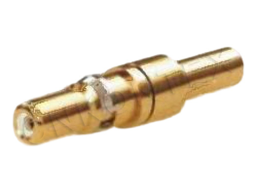
D4 RF Coaxial Connectors KTX D4-K3
The case for D4 is rarely about performance. It is about fit: an existing panel cutout, an existing cable assembly, an existing test procedure nobody wants to re-qualify. Where the 2 GHz ceiling is enough and the mechanical envelope is fixed, a
D4 RF coaxial connector from a supplier who publishes the interface dimensions is a low-risk purchase. Where any of those conditions changes, the honest answer is to move the design to an SMA or a QMA and stop maintaining a legacy interface for its own sake.
Zhenjiang Kontex Electronics manufactures the D4 series in Jiangsu and supplies it alongside the SMA, QMA, SSMA and SMC ranges, so a retrofit can be sourced from one place instead of three.