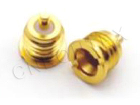
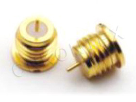
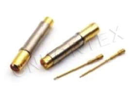
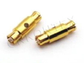
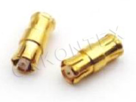
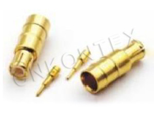
What Are MCX and MMCX Connectors?
The MCX connector is a snap-on (push-on) coaxial RF connector with a 50 Ω characteristic impedance, a frequency range up to 6 GHz, and a body size approximately 30 % smaller than SMA. MCX was developed in the 1980s as a smaller alternative to SMA for consumer electronics and compact industrial RF.
The MMCX connector is a micro-miniature variant of MCX with the same snap-on mechanism and 50 Ω impedance but a body size approximately 50 % smaller than MCX (and 70 % smaller than SMA). MMCX follows the same IEC 61169-8 standard family as MCX and is widely used in compact consumer devices.
Typical MCX and MMCX applications:
GPS modules and antennas.
Consumer Wi-Fi and Bluetooth modules.
Cellular modules (4G LTE, 5G NR FR1 small modules).
Compact wireless data terminals.
Medical devices (hearing aids, patient monitoring).
Industrial IoT and M2M modules.
Set-top boxes and satellite receivers.
Automotive infotainment (legacy).
The combination of small size, snap-on mating, and adequate RF performance for sub-6 GHz applications has made MCX and MMCX the dominant compact consumer RF interfaces.
How Does the Snap-On Mechanism Work?
MCX and MMCX use a snap-on coupling similar to SMB but smaller, with the plug's outer contact springing into a groove inside the jack to retain the connection. The snap-on mechanism allows quick mating without tools but has lower mating cycle durability than threaded coupling.
|
Mechanism |
Mating force |
Retention |
Tool required |
Cycle durability |
|
SMA (threaded) |
~15 in-lbs torque |
High (thread) |
Torque wrench |
≥ 500 |
|
MCX (snap) |
~10 N |
~30 N |
None |
≥ 500 |
|
MMCX (snap) |
~5 N |
~15 N |
None |
≥ 500 |
The snap-on mechanism is the major advantage in dense PCB layouts where individual SMA torque application would be impractical. It is also the major disadvantage in high-vibration applications where the connection may loosen.
What Are the Key Specifications?
MCX and MMCX specifications are similar to SMA in the sub-6 GHz range, with the main differences being frequency ceiling, power handling, and mating cycle durability. The electrical performance below 6 GHz is generally equivalent to SMA.
|
Specification |
MCX |
MMCX |
SMA |
|
Frequency range |
DC – 6 GHz |
DC – 6 GHz |
DC – 18 GHz |
|
Characteristic impedance |
50 Ω |
50 Ω |
50 Ω |
|
VSWR (DC – 3 GHz) |
≤ 1.15 |
≤ 1.15 |
≤ 1.15 |
|
VSWR (3 – 6 GHz) |
≤ 1.30 |
≤ 1.30 |
≤ 1.20 |
|
Insertion loss (DC – 3 GHz) |
≤ 0.10 dB |
≤ 0.10 dB |
≤ 0.10 dB |
|
Insertion loss (3 – 6 GHz) |
≤ 0.20 dB |
≤ 0.20 dB |
≤ 0.15 dB |
|
Power handling (CW @ 1 GHz) |
~50 W |
~30 W |
~200 W |
|
Mating cycles |
≥ 500 |
≥ 500 |
≥ 500 |
|
Body OD (typical plug) |
~3.5 mm |
~2.5 mm |
~7 mm |
|
Coupling |
Snap-on |
Snap-on |
Threaded |
For sub-6 GHz applications, MCX and MMCX provide essentially the same electrical performance as SMA in a much smaller package, at the cost of power handling and ruggedness.
When Should You Choose MCX?
MCX is the right choice for compact consumer and industrial RF applications up to 6 GHz where space is constrained, snap-on mating is acceptable, and power handling of ~50 W CW is sufficient. MCX is the standard interface for many consumer electronics.
Decision factors:
Frequency. Up to 6 GHz (covers all sub-6 GHz consumer wireless).
Mating. Snap-on, no tools required.
Power. ~50 W CW at 1 GHz.
Size. 30 % smaller than SMA.
Cost. Lower than SMA.
Application. Consumer electronics, GPS modules, Wi-Fi modules.
MCX is widely used in GPS modules (where the antenna cable connects to the module), in cellular modules for IoT, and in compact test fixtures.
When Should You Choose MMCX?
MMCX is the right choice for ultra-compact RF applications where MCX is still too large, with the body size 50 % smaller than MCX and 70 % smaller than SMA, while maintaining 6 GHz performance. MMCX is the standard for compact consumer devices.
Decision factors:
Frequency. Up to 6 GHz.
Mating. Snap-on, no tools required.
Power. ~30 W CW at 1 GHz (lower than MCX).
Size. 50 % smaller than MCX.
Cost. Lower than MCX.
Application. Compact consumer devices, hearing aids, IoT.
MMCX is widely used in hearing aids, compact GPS trackers, and ultra-compact consumer devices where every millimeter of board space matters.
When Should You Choose SMA?
SMA is the right choice for full-performance RF applications up to 18 GHz where threaded coupling, higher power handling (~200 W CW), and rugged mechanical durability are required. SMA remains the default for most microwave test and measurement, aerospace, and 5G infrastructure.
Decision factors:
Frequency. Up to 18 GHz (precision to 26.5 GHz).
Mating. Threaded, requires torque wrench.
Power. ~200 W CW at 1 GHz.
Size. Larger than MCX/MMCX.
Cost. Higher than MCX/MMCX.
Application. Microwave test, aerospace, 5G infrastructure.
For applications requiring both small size and high performance (e.g., a portable 18 GHz spectrum analyzer), there is no ideal alternative — the trade-off must be evaluated.
What Are the Mechanical Limitations?
MCX and MMCX have three main limitations: lower mating cycle durability in production environments, lower vibration resistance due to snap-on mechanism, and difficulty in field service without specialized tools. Each limitation is addressable.
|
Limitation |
Cause |
Mitigation |
|
Lower vibration resistance |
Snap-on mechanism can loosen |
Mechanical locking accessory; conformal coating |
|
Limited mating cycles |
Spring contact wear |
Use MMCX with locking accessory; replace as service part |
|
Difficult field service |
No tool-less unmating |
Use extractor tool; design for module replacement |
|
Power limit |
Small center pin |
Use SMA or N-Type for high-power applications |
|
Frequency limit |
Geometry |
Use SMA, 2.92 mm, or 1.85 mm for > 6 GHz |
For vibration-sensitive applications (automotive, industrial), SMA's threaded coupling is preferred over MCX/MMCX. Kontex's MCX/MMCX Series includes locking accessories for vibration-prone applications.
How Does Size Affect PCB Layout?
MCX and MMCX occupy significantly less PCB real estate than SMA, allowing higher-density layouts with more channels per board area, at the cost of requiring tighter PCB-launch design and smaller trace widths.
|
Connector |
Body footprint (typ.) |
Trace width (50 Ω, FR4 0.8 mm) |
Recommended via fence pitch |
|
SMA (vertical PCB) |
~12 × 12 mm |
~1.5 mm |
~2 mm |
|
MCX (vertical PCB) |
~7 × 7 mm |
~1.0 mm |
~1.5 mm |
|
MMCX (vertical PCB) |
~5 × 5 mm |
~0.8 mm |
~1.2 mm |
For high-density layouts (e.g., 4×4 MIMO modules with 4 RF channels), MCX or MMCX allows the channels to fit in the available footprint. SMA would require a larger board.
What Are the Standard Mounting Styles?
MCX and MMCX are available in PCB-mount (vertical, right-angle, edge-mount), cable-mount, and panel-mount styles, with PCB-mount being the dominant configuration. Kontex's MCX/MMCX Series covers all standard mounting styles.
|
Mounting style |
MCX |
MMCX |
Application |
|
PCB vertical jack |
Yes |
Yes |
PCB launch, vertical |
|
PCB right-angle jack |
Yes |
Yes |
PCB launch, parallel |
|
PCB edge-mount jack |
Less common |
Yes |
Compact modules |
|
Cable straight plug |
Yes |
Yes |
Cable termination |
|
Cable right-angle plug |
Yes |
Less common |
Tight routing |
|
Panel-mount jack |
Yes |
Less common |
Panel feed-through |
|
In-line adapter |
Yes |
Less common |
Cable extension |
For consumer modules, PCB right-angle MMCX is the most common configuration because it allows the cable to exit parallel to the board, reducing overall height.
What Cables Are Compatible?
MCX and MMCX are designed for small-diameter flexible coaxial cables (typically RG-174, RG-178, RG-316, RD-316) with the specific cable group depending on the connector's cable-entry design. Smaller cable diameter is required for the smaller connector body.
|
Cable |
OD (mm) |
Impedance |
Frequency limit |
Typical use |
|
RG-178 |
1.85 |
50 Ω |
3 GHz |
Very thin, tight routing |
|
RG-174 |
2.6 |
50 Ω |
3 GHz |
Low-power, flexible |
|
RG-316 |
2.6 |
50 Ω |
3 GHz |
Low-power, flexible |
|
RD-316 |
2.9 |
50 Ω |
3 GHz |
Double-shielded |
|
RG-188 |
2.6 |
50 Ω |
3 GHz |
High-temperature |
|
RG-316 DS |
3.0 |
50 Ω |
6 GHz |
Double-shielded, higher freq |
|
LMR-100 |
2.8 |
50 Ω |
6 GHz |
Low-loss, flexible |
For 6 GHz applications, LMR-100 or RG-316 DS is preferred. For 3 GHz applications, RG-174 or RG-316 is standard.
How Do They Compare to Other Compact Connectors?
MCX and MMCX sit between SMB (larger, more rugged) and U.FL / MHF (much smaller, lower power) in the miniaturized RF connector hierarchy, with each step providing smaller size at the cost of ruggedness and power. Kontex's MCX/MMCX Series provides MCX and MMCX for compact applications.
|
Connector |
Frequency |
Body OD |
Power (CW @ 1 GHz) |
Mating cycles |
Application |
|
SMA |
18 GHz |
~7 mm |
~200 W |
≥ 500 |
Microwave, base-station |
|
SMB |
4 GHz |
~5 mm |
~100 W |
≥ 500 |
Industrial, automotive |
|
MCX |
6 GHz |
~3.5 mm |
~50 W |
≥ 500 |
Consumer, IoT |
|
MMCX |
6 GHz |
~2.5 mm |
~30 W |
≥ 500 |
Compact consumer |
|
U.FL / MHF |
6 GHz |
~2.0 mm |
~10 W |
≥ 30 |
Ultra-compact consumer |
For ultra-compact applications (smartphone, tablet), U.FL / MHF is used. For compact applications (IoT module, hearing aid), MMCX is used. For general consumer, MCX is standard.
Frequently Asked Questions
Q: What is the difference between MCX and MMCX?
A: MCX is the larger version (~3.5 mm body OD) with higher power (~50 W CW). MMCX is the micro version (~2.5 mm body OD) with lower power (~30 W CW). Both share the same basic snap-on mechanism and 6 GHz frequency limit.
Q: Can MCX and MMCX mate?
A: No. MCX and MMCX are mechanically incompatible due to body size differences. An MCX-to-MMCX inter-series adapter is required for transitions.
Q: Are MCX and MMCX mate-compatible with SMB?
A: No. SMB is mechanically different (different snap-on groove geometry) and is not mate-compatible with MCX or MMCX.
Q: What is the frequency limit for MCX?
A: Standard MCX is rated to 6 GHz. For applications above 6 GHz, use SMA (to 18 GHz) or 2.92 mm (to 40 GHz).
Q: Can MCX be used for power?
A: MCX can handle ~50 W CW at 1 GHz, decreasing with frequency. For applications requiring higher power, use SMA (~200 W), N-Type (~300 W), or 7/16 DIN (~1500 W).
Q: Is MMCX vibration-resistant?
A: Standard MMCX has limited vibration resistance due to its snap-on mechanism. For vibration-prone applications, use MMCX with a locking accessory or use SMA (threaded) instead.
Q: What is the maximum mating cycle for MMCX?
A: Standard MMCX is rated for ≥ 500 mating cycles. The snap-on mechanism is the wear element; replace the connector as a service part when mating force decreases.
Q: Can I use an MCX-to-SMA adapter?
A: Yes. MCX-to-SMA inter-series adapters are widely available and are commonly used to connect compact consumer modules to standard test equipment. The adapter adds an interface and slightly degrades VSWR and PIM. Kontex's RF Adapter Series includes standard MCX-to-SMA adapters.
Q: Does Kontex offer custom MCX/MMCX configurations?
A: Yes. Kontex offers custom MCX/MMCX configurations including custom PCB-launch geometries, right-angle and edge-mount versions, and locking accessories. Contact the Kontex engineering team for custom requirements.
Conclusion
MCX and MMCX are miniaturized alternatives to SMA for compact consumer and industrial RF applications up to 6 GHz, providing snap-on mating and 30–70 % smaller body size at the cost of power handling and ruggedness. The choice depends on the application's priority: MCX for general compact consumer, MMCX for ultra-compact devices, SMA for full performance up to 18 GHz. Kontex's MCX/MMCX Series provides the full range with matching PCB-mount and cable-mount configurations, complemented by the SMA Series for full-performance applications and the RF Adapter Series for inter-series transitions. For product range, certifications, and engineering support, consult the Field Application and About pages.