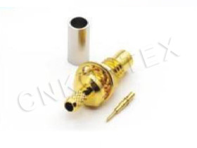
SMC RF Connectors: 11 GHz Performance In A 3.7 Mm Body
Release time:2026-11-23
Visits:25
There is a narrow slot in connector selection between the SMB, which is comfortable to about 4 GHz, and the SSMA, which reaches 30 GHz but asks for a threaded coupling and a careful assembly technician.
SMC RF connectors sit in that slot. They use a snap-on coupling, keep a body around 3.7 mm across, and carry a usable specification to 11 GHz. For instrumentation front ends, medical imaging modules and compact radio hardware, that combination solves a problem the neighbouring families do not.
The Electrical Case
KONTEX publishes the following for the SMC series. These are the numbers to design against.
|
Parameter |
Value |
|
Characteristic impedance |
50 Ω |
|
Frequency range |
DC – 11 GHz |
|
VSWR |
≤ 1.25 / ≤ 1.35 |
|
Voltage rating |
250 V |
|
Dielectric withstanding voltage |
750 V |
|
Insulation resistance |
≥ 1000 MΩ |
|
Durability |
500 mating cycles |
|
Temperature range |
−65 °C to +165 °C |
Two VSWR Limits, Two Meanings
The series quotes two VSWR figures because two mechanical configurations exist: a straight connector and a right-angle one. The straight part holds the tighter number because the inner conductor runs in a straight line from cable to interface. The right-angle part has a bend, and the bend is a discontinuity that cannot be tuned away inside a body this small. When a design is marginal at 10 GHz, switching a right-angle SMC for a straight one with a cable loop is often the cheapest fix available.
The Temperature Range Is the Quiet Advantage
A −65 °C to +165 °C rating is wider than most commercial parts and wider than many military ones. It comes from the PTFE dielectric and the metal system rather than from anything exotic. For a connector that will be potted into a module, cycled in an environmental chamber, or mounted near a heat source, that range is a real specification and not a marketing line. Thermal cycling also exposes plating problems, so if the assembly will be cycled, qualify it cycled rather than at room temperature.
250 V and 750 V Are Not the Same Number
The 250 V rating is the working voltage; the 750 V figure is a dielectric withstanding test applied for a short period. Confusing them is a common documentation error. Design the insulation gap for the working voltage with margin, and use the withstand figure as a production test limit, not as an operating condition.
The Snap-On Coupling and What It Costs
An SMC pair engages with a push and releases with a pull. There is no coupling nut, so the connector is shorter than a threaded equivalent and can be mated in places a wrench will never reach.
Where the Speed Pays
Test fixtures, modular instruments and any product that is assembled and disassembled during service benefit most. A snap-on interface removes a torque step from the work instruction, and removing a step removes a class of defects: cross-threading, under-torque and over-torque all disappear.
Where It Does Not
Snap-on interfaces have lower retention force than threaded ones and less resistance to a steady side load. On a cable that hangs from a panel, the connector becomes a pivot and the cable becomes a lever. Support the cable within a short distance of the connector, and never use the connector as the strain relief. In vibration environments, add a clamp and check retention after the vibration test rather than before.
The Range and What Each Part Is For
The KTX SMC range is organised around the cable it terminates and the direction the cable leaves.
|
Part |
Notes |
|
KTX SMC-JY3 |
Straight cable connector |
|
KTX SMC-JW3 |
Right-angle cable connector |
|
KTX SMC-K3 |
Mating jack |
|
KTX SMC-KW3 |
Right-angle jack |
|
KTX SMC-JY1.37 |
For 1.37 mm micro-coax |
|
KTX SMC-K-3 |
Jack variant for panel or housing use |
|
KTX SMC-K174 |
For RG174-class cable |
|
KTX SMC-JE Lengthened |
Extended body for thicker walls |
The 1.37 mm and RG174 versions are worth pointing out, because they define the two cable worlds this connector lives in. A 1.37 mm micro-coax suits a dense module where the harness has to bend inside a small volume; an RG174-class cable suits a short external jumper where robustness matters more than loss. Both are single-braid constructions, so the shield termination — not the connector body — usually sets the shielding performance of the assembly.
The Lengthened Version
The extended-body variant exists for a mundane and important reason: panel thickness. A standard body assumes a thin wall. When a housing wall is thicker, or when a connector has to pass through a casting with a boss, the lengthened version keeps the mating plane where the drawing says it is instead of recessing the interface inside a hole.
Applications Where the Fit Is Right
Instrumentation and Test
A snap-on 11 GHz interface is close to ideal for a bench instrument that is connected and disconnected many times a day. The 500-cycle rating is the constraint to watch: a connector used ten times a day reaches it in under three months. Treat the panel connector as a consumable and plan to replace it, or specify a threaded interface for the panel and keep the snap-on at the module end.
Medical and Industrial Imaging
Small body, wide temperature range, and a coupling that can be mated by a technician wearing gloves. These are the reasons SMC appears in probe heads and imaging modules, where the connector has to survive repeated connection by hand and still hold its return loss.
Compact Radio Hardware
Below 11 GHz there is a large amount of hardware that does not need an SMA: telemetry, short-range links, antenna monitoring.
SMC RF connectors give the same impedance and a similar loss in a smaller envelope, at the cost of retention force and a lower cycle rating. For a product that ships in volume, that trade is often the difference between a harness that fits inside the housing and one that does not.
Assembly Notes
Crimp or solder the centre pin at the depth the drawing specifies; at 10 GHz a recessed pin is a measurable reflection. Keep the braid termination short and 360 degrees — a pigtail shield connection turns the assembly into an antenna above a few gigahertz. Check the mating face for flash after moulding, because a snap-on interface has no thread to force its way past a burr. And measure a sample: a sweep to 11 GHz on the first ten assemblies will tell you more about your process than any incoming inspection.
KONTEX manufactures the SMC series at its Zhenjiang facility in Jiangsu, alongside the SMB, SSMB, SSMA and SMA ranges, and publishes the electrical table and interface dimensions needed to design a part in without a sample round.