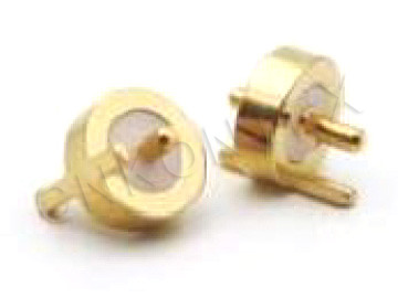
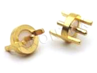
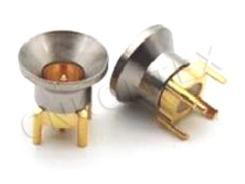
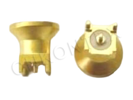
MMBX RF Connectors At 12.4 GHz: What The Performance Numbers Mean
Release time:2026-12-07
Visits:30
A connector that quotes VSWR 1.06 looks like a solved problem. It is not. That figure describes a well-made pair mated correctly, mounted on a launch that behaves, measured with a calibration that ends at the right plane. Change any of those four conditions and the number moves. Understanding why is the difference between using
MMBX RF connectors successfully and arguing with a supplier about a measurement neither side can reproduce.
What the 12.4 GHz Ceiling Represents
The interface is a micro-miniature bayonet coaxial pair with a 50 ohm characteristic impedance. Its upper frequency limit of 12.4 GHz is not a plating limit or a loss limit — it is where the cross-section stops supporting a clean TEM mode and higher-order modes begin to propagate.
Why Size and Bandwidth Trade
A smaller coaxial cross-section pushes the first higher-order mode up in frequency, which is why shrinking a connector raises its usable band. MMBX takes that to the practical limit for a snap-on part: any smaller and the mechanical tolerances become impossible to hold in production. Below 12.4 GHz the interface is electrically short and behaves predictably; above it, the geometry itself generates resonances that no amount of tuning removes.
What That Means for a Design
If a link needs 15 GHz, do not look for a better
MMBX. Move to a family designed for the band, and accept the larger body. If a link needs 10 GHz, an MMBX has margin — and margin is what allows a launch that is good rather than perfect.
The Electrical Picture
|
Parameter |
Value |
|
Characteristic impedance |
50 Ω |
|
Frequency range |
DC – 12.4 GHz |
|
VSWR |
around 1.06 : 1 |
|
Contact material |
gold-plated beryllium copper |
|
Coupling |
bayonet, snap-on |
|
Typical application |
board-to-board, coax-to-PCB, module test |
VSWR 1.06 and Return Loss
A VSWR of 1.06 corresponds to a return loss of roughly 30 dB, which is a reflection coefficient near 0.03. In a system with a 10 dB link margin that is irrelevant; in a measurement path that needs 40 dB of dynamic range it is the dominant error. Know which of those two systems you are building before deciding whether the number is good enough.
Gold on Beryllium Copper
The contact system is gold-plated beryllium copper. Beryllium copper keeps its spring over repeated mating, and gold keeps the contact resistance stable at low signal levels. That combination is why the same connector can be used in a receive path carrying microvolts and in a transmit path carrying watts: the interface does not care about the signal level, only about the contact quality.
Insertion Loss Is Small and Cumulative
The connector's own insertion loss is a fraction of a decibel at 12 GHz. Two connectors, two launches and a short cable add up to something measurable. In a test path, the connector loss is the part that gets forgotten when the budget does not close.
The Launch Is the Real Variable
Most "bad connector" measurements are bad launches. On a board, the transition from a microstrip or coplanar line into the connector is a discontinuity, and at 12 GHz it is a significant one.
Ground Vias and Reference Planes
Place ground vias within one dielectric thickness of the connector body, on both sides of the launch, tied to the plane the trace references. A launch that relies on distant vias will resonate below 12 GHz, and the resonance will look exactly like a connector problem when swept through a cable.
Pad Geometry
The signal pad should be as close to the connector's centre pin diameter as the fabrication process allows. A pad that is much wider than the pin creates a capacitance at the transition; a pad that is much narrower creates an inductance. Both show up as a tilt in the return loss curve rather than a spike, which makes them easy to mistake for a cable issue.
Coplanarity and Seating
A surface-mount part that sits 0.1 mm high changes the launch geometry. Check coplanarity before reflow and inspect the fillets afterwards. On a blind-mate pair, a partial engagement has the same effect and is harder to see.
Measuring Without Fooling Yourself
|
Pitfall |
What it looks like |
How to avoid it |
|
Calibration plane too far back |
Flat, optimistic return loss |
Calibrate to the connector plane or de-embed |
|
Cable movement during sweep |
Noisy trace, drifting ripple |
Clamp the cable, use a torque-free support |
|
Mating only once |
Random results across parts |
Mate three times, record the worst case |
|
Dirty interface |
Loss that improves after cleaning |
Cap parts, clean before mating |
|
Adapters in the path |
Ripple with a fixed period |
Count adapters, remove them from the reference |
De-Embedding, Briefly
If the measurement has to describe the connector and not the fixture, the fixture has to be characterised and removed. For most product work that is overkill: what matters is whether the assembled link meets its specification. For a component qualification, it is not optional — and it is the reason two suppliers can quote the same VSWR and measure differently.
Test Boards and Fixtures
A KTX MMBX connector makes a good test point because it is small, self-aligning and rated for repeated mating. Two practices keep a test board honest over its life.
First, treat the test connector as a consumable. Count mates and replace on a schedule, not on failure. A fixture connector can see more cycles in a month than a product sees in a decade, and the 500-cycle class of rating is not a licence to ignore it.
Second, keep a reference artefact. A short known-good jumper, measured every week, tells you whether a change in results came from the device under test or from the fixture.
Specifying MMBX RF Connectors
Ask for four things: the frequency at which VSWR is guaranteed, the mating tolerance in both tilt and radial offset, the recommended footprint and keep-out, and the plating specification. A supplier who can answer all four has done the engineering; one who answers only the first has copied a catalogue.
KONTEX manufactures
MMBX RF connectors, board jacks and adapters in Zhenjiang, Jiangsu, as part of a range that also covers MBX, SSMA, SMC and SMA interfaces. For a design that has to hold performance to 12.4 GHz in a body a few millimetres across, the connector is the easy part — the launch, the stack and the measurement discipline are where the work is.