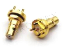
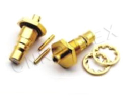
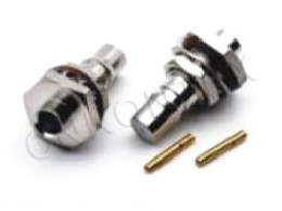
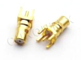
SSMB Cable Assemblies: Terminating A Snap-On Interface To Cable
Release time:2026-11-27
Visits:24
A connector on a datasheet and a connector on the end of a cable are two different products. The first is a set of dimensions and materials; the second is a mechanical joint that has to survive being pulled, bent, cycled and measured. SSMB cable assemblies live or die on that joint. The interface itself is well defined — a snap-on sub-miniature coaxial pair standardised under IEC 60169-19 — but most of the failures that reach a customer trace back to how the cable was prepared and terminated, not to the interface.
Why SSMB Suits an Assembly Business
The SSMB interface was developed in the mid-1990s and standardised as IEC 60169-19. It takes the SMB idea and shrinks it, keeping a snap-on coupling while reducing the body. For an assembly builder, three properties matter.
No Torque in the Work Instruction
A snap-on coupling removes a torque step from assembly and from service. On a production line that means one fewer tool, one fewer gauge, and one fewer defect class. In the field it means a technician can replace a jumper without a wrench, which is often the difference between a ten-minute service call and a return-to-depot repair.
A Defined VSWR Ceiling
The published limits are useful because they separate straight from right-angle parts. A straight
SSMB holds VSWR at or below 1.22 from DC to 1 GHz and 1.35 to 3 GHz. A right-angle part allows 1.50 and 1.63 over the same bands. That gap is the cost of the bend, and it is worth designing around: if a run can use a straight connector and a cable loop instead of a right angle, the loss budget improves for free.
Enough Cycles for Real Service
The 500-cycle durability rating is generous for a product connector and tight for a test port. Classify each connector in the bill of materials by how often it will be mated, and specify accordingly.
The Electrical Target
|
Parameter |
Value |
|
Characteristic impedance |
50 Ω |
|
Insulation resistance |
≥ 1000 MΩ |
|
Dielectric withstanding voltage |
500 V |
|
VSWR, straight, DC – 1 GHz |
≤ 1.22 |
|
VSWR, straight, DC – 3 GHz |
≤ 1.35 |
|
VSWR, right angle, DC – 1 GHz |
≤ 1.50 |
|
VSWR, right angle, DC – 3 GHz |
≤ 1.63 |
|
Contact resistance, inner conductor |
≤ 0.005 Ω |
|
Contact resistance, outer conductor |
≤ 0.0025 Ω |
|
Durability |
500 mating cycles |
|
Temperature range |
−55 °C to +155 °C |
The contact resistance limits are the ones that catch process problems early. Five milliohms on the inner conductor is easy to hit with a good crimp and easy to miss with a poor solder joint that still looks connected. Measure it on the first article, then sample.
Building the Assembly
Choosing the Cable Before the Connector
SSMB is normally terminated to micro-coax: 1.37 mm, RG178, RG316 and similar single-braid constructions. The cable choice sets three things the connector cannot fix: loss per metre, bend radius and shielding effectiveness. A 1.37 mm cable has a tight bend radius and higher loss; an RG316-class cable is more robust and lossier still at 3 GHz. Decide the cable on mechanical routing first, then check the loss at the top of the band.
Crimp or Solder
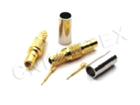
Crimp is the production answer: repeatable, inspectable, and fast. Solder is the prototype answer, and it is also the answer when the cable is a semi-rigid or a construction that cannot be crimped reliably. Whichever route is chosen, the centre pin depth is the critical dimension. A pin that sits 0.2 mm short of the mating plane produces a reflection that no amount of cable tuning removes, and it is invisible to a continuity test.
Strip Lengths and the Shield
The braid termination decides the shielding performance of the whole assembly. Keep it short and 360 degrees. A pigtail — a few strands folded back and soldered — is acceptable at audio frequencies and a radiator at 2 GHz. If the assembly has to hold a shielding figure, the ferrule has to clamp the braid all the way round, with no dielectric trapped underneath.
Strain Relief and Overmoulding
A snap-on connector relies on the cable for mechanical stability. Add a boot or an overmould that transfers load from the cable jacket to the connector body, and specify a bend radius in the drawing so the harness shop does not have to guess. For outdoor or washdown use, a sealed boot plus a capped mating face is the minimum.
What to Put on the Drawing
An assembly drawing that leaves these items out will produce a different product at every build.
|
Item |
Specification to state |
|
Cable type and length |
Part number plus length with tolerance |
|
Connector pair |
Both ends, including straight or right angle |
|
VSWR limit |
Per band, per connector style |
|
Insertion loss |
Maximum at the top of the band |
|
Pull force |
Minimum axial force without damage |
|
Marking and test label |
Traceable to the build lot |
Length Tolerance Is Not a Detail
At 3 GHz, 10 mm of length is roughly 2 degrees of phase. For a phase-matched pair, the tolerance has to be in the drawing and the measurement has to be on a network analyser, not a tape measure. For a single jumper, a ±3 mm tolerance is usually enough — but write it down.
Failure Modes Worth Knowing
|
Symptom |
Likely cause |
Fix |
|
VSWR rises after a few mates |
Pin depth drifting, socket losing tension |
Check strip length and crimp height |
|
Intermittent at high vibration |
Braid not clamped 360°, boot too stiff |
Change ferrule, soften the boot |
|
Loss higher than calculated |
Wrong cable, long pigtail shield |
Recalculate with the actual construction |
|
Connector pulls off |
Jacket not captured by the boot |
Add a jacket crimp or overmould |
Sourcing SSMB Cable Assemblies
Two questions sort suppliers quickly. Ask whether the VSWR limit is guaranteed per band and per connector style, not as a single number for the assembly. And ask for the interface dimensions, because an assembly built to a lookalike interface will mate with the real thing just often enough to be dangerous.
KONTEX builds
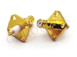
SSMB connectors and terminates them into custom assemblies at its Zhenjiang facility in Jiangsu, with the connector range — straight, right-angle, flange and jack versions — and the cable assembly line under one roof. That matters for an assembly programme: when the connector and the termination are made by the same supplier, a VSWR problem has one owner instead of two.