SSMA Connector: Mating Dimensions And Torque Discipline
Release time:2026-12-04
Visits:28
A 30 GHz link has very little tolerance for a connector that is almost seated. At that frequency a fraction of a millimetre of axial error, or a body distorted by an over-tightened nut, shows up as return loss that no cable specification can explain. The
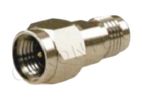
SSMA connector is a good interface — small, threaded, and specified to 30 GHz — and it is also one of the easier ones to install badly, because the nut is small enough to encourage tightening by feel.
The Thread Sets the Rules
SSMA uses a 10-36UNS coupling thread, smaller than the SMA's 1/4-36UNS. The change buys a smaller body and a shorter dielectric path, which is what pushes the usable band from 18 GHz to 30 GHz.
Why the Thread Matters More Than the Nut
The thread is the reference. When a plug and jack are fully engaged, the thread positions the two mating planes, and the shoulder of the coupling nut stops further travel. Anything that interferes with that — a burr on the first thread, grit in the groove, a nut started at an angle — moves the reference plane and changes the impedance at the launch.
What the Interface Values Describe
The published interface drawing uses symbols a through W. The values below are the ones that drive mechanical design and inspection.
|
Feature |
Value |
|
Coupling thread |
10-36UNS-2A (plug) / 10-36UNS-2B (jack) |
|
Centre conductor diameter |
φ0.85 – 0.88 mm |
|
Dielectric outer diameter |
φ3.15 – 3.22 mm |
|
Outer body diameter |
φ4.98 – 5.13 mm |
The remaining symbols locate shoulders, steps and the seating depth. They matter to a manufacturer and to anyone doing a first-article inspection; for a designer, the four above explain the part's behaviour. The centre conductor at 0.85 to 0.88 mm is a thin pin — thinner than an SMA's — and the dielectric around it is what holds 50 ohms. A body only 5 mm across has very little material to absorb mechanical abuse.
Where the Electrical Limits Come From
|
Parameter |
Value |
|
Characteristic impedance |
50 Ω |
|
Frequency range |
DC – 30 GHz |
|
VSWR |
≤ 1.07 + 0.01 F (GHz) |
|
Insulation resistance |
≥ 1000 MΩ |
|
Dielectric withstanding voltage |
750 V |
|
Contact resistance, inner conductor |
≤ 0.006 Ω |
|
Contact resistance, outer conductor |
≤ 0.0025 Ω |
|
Durability |
500 mating cycles |
|
Temperature range |
−55 °C to +155 °C |
The VSWR formula is a straight line, and it is deliberately honest: 1.08 at 1 GHz, 1.37 at 30 GHz. Read it as a budget rather than a target. A mated pair that measures 1.30 at 26 GHz is inside the specification and still contributes a noticeable reflection to a link that also has a right-angle bend and an adapter in it.
Torque, Engagement and the Failure Nobody Sees
Under-Torque
An under-torqued
SSMA connector can pass a continuity test and still be wrong. The reference planes are not in contact, the outer conductor path has a gap, and the result is a reflection plus a leakage path. On a receiver front end, that shows up as a noise floor that moves when the cable is touched.
Over-Torque
Over-torque is worse, because it is permanent. The nut is small, the body wall is thin, and the thread is fine. Excess torque distorts the body, tilts the mating plane, and sometimes cracks the dielectric. The connector still mates and still measures acceptably at low frequency; the damage appears as a VSWR bump near the top of the band, where the geometry error is a significant fraction of a wavelength.
The Practical Rule
Use a small torque wrench set to the value the connector supplier specifies, and stop when it clicks. If a wrench is not available, hand-tight plus a small fraction of a turn is safer than a firm pull on a short spanner. Never use pliers on a coupling nut, and never use the cable as a lever to gain purchase.
Bulkhead and Panel Mounting
An
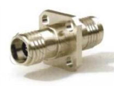
SSMA bulkhead connector passes through a panel and presents a mating face on both sides. Two things go wrong routinely.
The first is the panel hole. An oversized hole lets the body shift under torque, so the interface is never square to the panel. The second is the locknut and washer stack: a thin panel needs a washer to spread the load, and a thick panel needs a longer body. Both are drawing items, not assembly preferences.
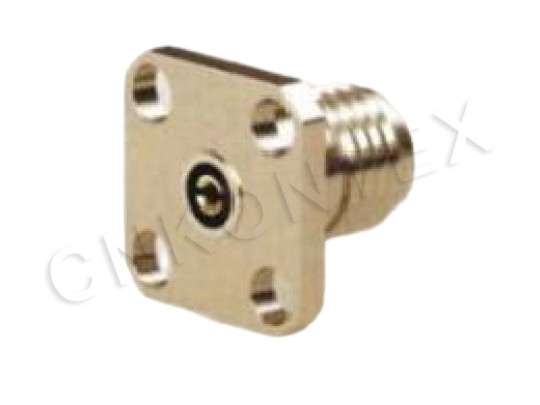
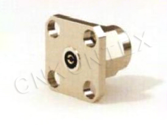
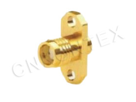
For flange-mounted versions, torque the four screws in a cross pattern and check the mating face with a straight edge afterwards. A flange pulled down on one side tilts the interface by an amount that is easy to measure and impossible to tune out electrically.
Cable Side Practice
Strip and Pin Depth
The centre pin has to reach the mating plane. On a 30 GHz assembly, a recessed pin is a reflection and a protruding pin is a damaged jack on the next mate. Use a strip tool with a fixed blade and a go/no-go pin depth gauge on the first ten assemblies.
Support the Cable
The body is 5 mm across. A cable hanging from it is a lever, and the load lands on the thread and the dielectric. Clamp the cable within a short distance of the connector on any chassis run, and give the harness a service loop so that a pull on the cable does not translate into a pull on the interface.
Inspection That Finds Problems Before the Test Range Does
|
Step |
What to check |
Why |
|
Visual |
Thread start, plating, dielectric face |
Catches damage before mating |
|
Pin depth |
Go/no-go gauge on a sample |
Prevents reflection and jack damage |
|
Torque |
Wrench setting recorded per station |
Removes operator judgement |
|
Mate cycle |
Three mates before measurement |
Reveals a nut that binds |
|
Sweep |
VSWR to 30 GHz on a sample |
Confirms the whole chain, not the parts |
The last row is the only one that measures the product rather than the components. A sample sweep on every lot, with the result recorded, is what turns a specification into a process.
A Note on Choosing the Part
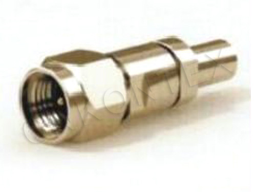
The KTX SSMA range covers cable, right-angle, flange and bulkhead configurations, and the choice between them is mostly mechanical: where the cable has to leave, and how the connector is held. Decide that first, then confirm the frequency at which the VSWR limit is guaranteed, then ask for the recommended torque. Those three answers, in that order, close a 30 GHz design review faster than any datasheet comparison.
Zhenjiang Kontex Electronics manufactures the SSMA connector series in Jiangsu alongside its SMA, SMC and QMA ranges, and publishes both the interface values and the electrical limits so that mating and measurement can be planned together.