MMBX Connectors: Series, Stack Height And Board Layout
Release time:2026-11-30
Visits:31
Once a product shrinks past a certain point, the coaxial connection stops being a cable decision and becomes a board decision.
MMBX connectors exist for that moment. They are the smaller end of the micro-miniature bayonet family: a 50 ohm interface that reaches 12.4 GHz, snaps together without tools, and occupies a footprint measured in a few millimetres. The engineering work shifts from cable routing to stack height, coplanarity and reflow.
The Series at a Glance
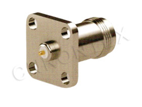
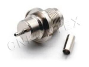
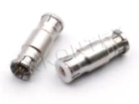
The KTX range covers the configurations that appear in real designs: board-mounted jacks, plugs, a board-to-board adapter and a panel version.
|
Part |
Role |
|
KTX MBX-J |
Board-mount jack |
|
KTX MBXJ |
Board-mount jack, alternate body |
|
KTX MMBX-JJ |
Board-to-board jack-to-jack adapter |
|
KTX MBX-KE2 |
Edge / PCB variant |
|
KTX MMBX-KE |
Edge / PCB variant |
|
KTX MBX-KE1 |
Edge / PCB variant, compact body |
|
KTX MMRX-KHD1 |
Panel-mount version |
The naming is worth decoding once, because it saves a round of emails. The J and K families separate the two mating halves; the E suffix points to a board or edge configuration rather than a cable termination; the JJ part is the adapter that joins two jacks and therefore sets the stack height between two boards.
Choosing the Pair
Three questions settle the selection. Does the signal leave the board (use a cable version) or stay on boards (use a board-to-board pair)? Is the second board parallel or perpendicular? Is there any chance the assembly will be opened in service? A parallel stack with a service requirement wants a jack-to-jack adapter and a floating allowance. A perpendicular connection usually wants an edge part.
Stack Height Drives Everything
In a board-to-board link, the connector pair fixes the distance between the two boards. That distance is not a preference — it becomes a constraint on standoff length, component height on both sides, and the housing design.
Set the Stack First
Decide the stack height before layout, then design the mechanical parts around it. Changing stack height later means changing both boards, the standoffs and the housing, which is the most expensive kind of late change in a hardware programme. Write the number on the mechanical drawing and treat it as a controlled dimension.
Tolerances That Eat the Allowance
The mated pair tolerates a small amount of misalignment — the bayonet family is specified with an allowance in the region of 4.5 degrees of tilt or 0.7 mm of radial offset, depending on the variant. That allowance is consumed by board thickness tolerance, standoff length tolerance, solder joint height, and housing flatness. Add them in the worst case before deciding the interface will find its own centre.
Layout Rules for the Footprint
Ground and Return Path
At 12 GHz the return current follows the launch, not the plane. Place ground vias within one dielectric thickness of the connector body, on both sides of the launch, and connect them to the plane that the signal actually references. A footprint with a generous signal pad and two distant ground vias will produce a resonance well below 12 GHz, and it will be blamed on the connector.
Keep-Out for the Coupling
The body is small; the coupling is not. Leave clearance for the plug's snap collar to expand and for a finger or a small tool to release it. On a crowded board the keep-out is usually the reason a part cannot be used, not the electrical performance.
Coplanarity
A surface-mount
MMBX part has to sit flat before reflow. Check the pad design against the part's leads or legs, and check the paste volume: too much paste lifts the body, too little starves a joint. On a thin board, add a local copper balance so the connector area does not warp during reflow.
Reflow, Cleaning and Handling
Cap the Interface
The interface is the most delicate feature on the part. Cap it during paste printing, reflow and board wash. Flux residue inside a bayonet coupling is a slow-acting failure: it attracts moisture, and moisture at 10 GHz is a dielectric change.
Do Not Use the Connector as a Pick Point
Micro-miniature connectors are not designed for nozzle placement. Specify a placement method that contacts the body sides, and check the first article for body tilt after reflow.
Rework
Removing a reflowed
MMBX connector usually destroys it. Design the board so that a damaged connector is either replaceable with hot-air rework and a fresh part, or accepted as a scrap board. Deciding this at layout time is cheaper than discovering it in production.
Electrical Expectations
|
Parameter |
Value |
|
Characteristic impedance |
50 Ω |
|
Frequency range |
DC – 12.4 GHz |
|
VSWR |
around 1.06 : 1 |
|
Contact material |
gold-plated beryllium copper |
|
Coupling |
bayonet, snap-on |
|
Typical application |
board-to-board, coax-to-PCB, module interconnect |
The 1.06 figure is achievable because the interface is electrically short. It is also easy to lose: a partially seated pair, a tilted body or a starved ground launch will each cost more return loss than the connector's own specification.
Where MMBX Connectors Fit Best
Modular Instruments and Test Boards
A snap-on board connector makes a module swappable without a cable. In a test environment, that is worth more than a fraction of a decibel: a module that can be changed in seconds gets changed, and hardware that gets changed gets debugged.
Antenna Modules and Front Ends
Array elements and front-end modules often need a connection that survives assembly and never needs to be touched again. A blind-mate pair is the right answer when the housing closes over the boards and the alignment is set by guide pins.
Dense Digital Boards With an RF Tap
Where a high-speed board needs one or two RF test points, an
MMBX connector gives a defined 50 ohm launch in a footprint small enough to place next to the digital circuitry. The limit is mechanical, not electrical: leave enough clearance for the mating plug and for the probe.
A Short Specification Checklist
Before releasing a drawing, confirm the stack height with the mechanical team, the footprint with the fabrication team, and the mating pair with the supplier. Ask for the recommended reflow profile and the keep-out envelope, not just the electrical table. And build one first article: mate it twenty times, sweep it to 12.4 GHz, and measure the seated height. Twenty minutes of that work replaces a page of assumptions.
KONTEX manufactures the MMBX and MBX series — board jacks, plugs, adapters and panel versions — in Zhenjiang, Jiangsu, and supplies them with the mating allowance and footprint data that a blind-mate design needs.