SMC Connector Dimensions: Reading The Interface And The Footprint
Release time:2026-11-16
Visits:25
A first note, because search engines mix two very different products under the same three letters. The dimensions on this page describe an SMC coaxial interface: a 50 ohm, snap-on, sub-miniature RF connector with a body around 3.7 mm across. If you arrived looking for a pneumatic push-to-connect fitting, the numbers below will not help you, and the tube diameters you need belong to a different catalogue.
For everyone else, the useful work is reading the drawing properly.
SMC connector dimensions are published as two symbol tables, one for each half of the mated pair, and almost every design error comes from reading a MIN where a MAX was intended.
Why the Interface Is Split Into Two Tables
A coaxial pair has two halves that have to do different jobs. One carries the centre pin and has to enter without stubbing; the other presents a bore and a shoulder and has to stop the pin at the right depth. Because the two halves are toleranced against each other, the supplier publishes them separately, using the same letters for related features.
Group 1: The Half With the Centre Pin
|
No. |
Dimension (mm) |
No. |
Dimension (mm) |
|
A |
φ0.25 MAX |
F |
3.4 MIN |
|
B |
φ0.48 – φ0.53 |
G |
0 MIN |
|
C |
φ2.08 MIN |
H |
0.25 MIN |
|
D |
φ3.71 MAX |
J |
2.13 MAX |
|
E |
3.4 MIN |
K |
5.94 MIN |
Symbol A is the centre pin, capped at 0.25 mm. That cap is not a nominal size — it is a ceiling, and the pin is normally made slightly under it so that it enters the mating bore with clearance. Symbol B, 0.48 to 0.53 mm, is the dielectric bore around the pin: a two-sided tolerance, which is why it is the dimension most sensitive to moulding and machining variation.
Symbol D, 3.71 mm maximum, is the one that gets used most often in mechanical design, because it defines the body envelope. Anything you place within 3.71 mm of the interface axis has to be checked against the mating plug's sweep.
Group 2: The Half That Receives It
|
No. |
Dimension (mm) |
|
A |
∅ 2.06 MAX |
|
B |
∅ 3.71 MIN |
|
C |
3.1 MAX |
|
D |
2.79 MIN |
|
E |
5.92 |
|
F |
3.4 MAX |
|
G |
3.4 MAX |
|
H |
0 MIN |
Group 2 repeats the exercise from the receiving side. A is a 2.06 mm maximum bore, B a 3.71 mm minimum shoulder, and C and D bracket the internal step that stops the pin at the correct depth. Note how B mirrors the plug's D: one is a maximum, the other a minimum, and the clearance between them is what allows the pair to mate at all.
Symbol E, at 5.92 mm with no tolerance band printed, is a reference dimension. It locates a feature relative to the mating plane and should be treated as nominal — do not build a tolerance stack on it.
How to Turn the Tables Into a Footprint
Start From the Mating Plane
Every other number is measured from the mating plane, the surface where the two halves touch. Draw that plane first, then place D (3.71 mm) as the body envelope, then place the panel or board features behind it. Designers who start from the panel cutout and work outward usually end up with an interface that is 0.3 mm too deep.
Derive the Panel Cutout, Do Not Copy It
The cutout has to clear the threaded or snap body and still leave a shoulder for the flange or nut to seat on. With a 3.71 mm maximum body, a cutout at 3.8 mm gives clearance but leaves almost no seating face; a cutout at 3.75 mm risks interference on the high side of the tolerance. The practical answer is to ask KONTEX for the recommended cutout for the specific part number rather than deriving it from the interface table, because the mounting hardware, not the interface, decides it. Reading
SMC connector dimensions is a five-minute exercise once the MIN and MAX logic is clear; guessing at a cutout can cost a rework cycle on every panel in the build.
Build the Stack in the Worst Case
Tolerance stack-ups on
SMC parts are short and easy to get wrong. Take the worst case in both directions: maximum body diameter against minimum cutout, minimum engagement against maximum panel thickness, maximum pin length against minimum bore depth. If the worst case still mates and still leaves the reference planes in contact, the design is sound. If it only works at nominal, it will fail on the first production batch.
The Electrical Numbers Behind the Dimensions
Dimensions exist to deliver an electrical result, and it helps to know which result each feature controls. The KTX SMC range from KONTEX is specified as follows.
|
Parameter |
Value |
|
Characteristic impedance |
50 Ω |
|
Frequency range |
DC – 11 GHz |
|
VSWR |
≤ 1.25 / ≤ 1.35 |
|
Voltage rating |
250 V |
|
Dielectric withstanding voltage |
750 V |
|
Insulation resistance |
≥ 1000 MΩ |
|
Durability |
500 mating cycles |
|
Temperature range |
−65 °C to +165 °C |
The centre pin diameter and the dielectric bore together set the characteristic impedance. Change either and the 50 ohm line becomes something else at the interface, which is why a replacement part with the same outline but a different B dimension can show a VSWR bump that no amount of cable tuning will remove. The 250 V rating and the 750 V withstand figure are set by the dielectric wall thickness, which is bounded by C and D. The −65 °C to +165 °C range is a property of the PTFE dielectric and the plating system, and it is one of the widest in the small connector families.
Where the Dimensions Are Checked in Production
A dimension table is only useful if somebody measures against it. On a production line, five checks cover most of the risk, and they are worth writing into the inspection plan as named steps rather than as a general instruction to check the drawing.
The centre pin is measured at A on the plug, sampled per lot, because a pin that is long enough to stub the bore will pass a visual check and fail at 8 GHz. The dielectric bore is measured at B, both limits, because moulding flash there shifts the impedance. The body envelope is measured at D on both halves to catch interference with the mating shell. Engagement is checked at E and F under load, since an interface that only engages at nominal will lose contact wipe on the high side of the tolerance. And mated VSWR is swept to 11 GHz on a sample of finished assemblies, which is the only check that measures the product rather than the parts.
The last step is the one people skip. A part can pass every dimensional check and still fail at 8 GHz because the plating is thin or the dielectric is off-centre. Sweep a sample of finished assemblies, not just loose connectors.
What to Ask a Supplier for
Before releasing a drawing, ask for four documents: the interface table with tolerances for the exact part number, the recommended panel cutout, the PCB footprint if the part is board-mounted, and the plating specification. A supplier who publishes interface dimensions but not plating is telling you that contact resistance is somebody else's problem.
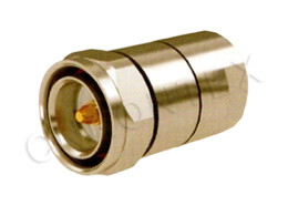
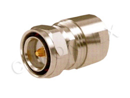
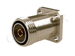
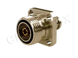
Zhenjiang Kontex Electronics publishes both dimension groups for its SMC series — the plug half and the jack half — along with the electrical table, and builds the range in Zhenjiang, Jiangsu. That combination lets a mechanical engineer close a drawing and an RF engineer close a link budget from the same document set, which is the point of publishing dimensions in the first place.