MBX Connector: The Mechanics Of A Blind-Mate Board Connection
Release time:2026-11-20
Visits:25
Two boards that have to be connected and then closed inside a housing create a problem that no cable can solve. Nobody can reach the connector once the assembly is together, and the alignment between the two halves is set by standoffs, guide pins and the tolerance of the housing rather than by a human hand. This is the job an
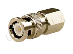
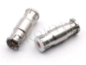
MBX connector is built for: a bayonet-coupled, micro-miniature coaxial interface that finds its own centre and snaps home when the two boards come together.
What Blind Mating Really Requires
The phrase gets used loosely. In practice, blind mating is a set of mechanical allowances that have to be designed in before the connector is chosen.
Radial Offset and Angular Tilt
An MBX pair tolerates misalignment of up to about 4.5 degrees of angular tilt, or 0.7 mm of radial offset, depending on which variant and which direction you measure. Those numbers look generous on paper and disappear quickly in a real stack. Every plate in the stack contributes: board thickness tolerance, standoff length tolerance, connector solder height, housing flatness, and the clearance in the guide pins. Add them in the worst case before assuming 0.7 mm is available.
Float Versus Fix
There are two ways to make a blind mate work. One is to let one half float — mounted in a slot or on a compliant bracket — so it can chase the other half. The other is to fix both halves and rely on the tolerance budget. Floating halves are more forgiving and harder to keep electrically stable, because a moving ground path is an intermittent ground path. Fixed halves are electrically cleaner and demand a tighter mechanical design. Most production hardware fixes the jack and floats the plug, so the centre pin leads the way into the bore.
Inside the Interface
MBX and its smaller MMBX relative share a bayonet-style coupling: a plug with a snap feature and a jack with a matching groove. Push, and the coupling engages with an audible and tactile click; pull, and it releases. No threads, no torque, no tool.
Why the Bayonet Suits Automation
A threaded interface cannot be mated blind, because the threads have to find each other before anything else happens. A bayonet coupling does not care about rotation — it engages at any angle, which is exactly what a pick-and-place assembly and a hand-closed housing need. The same property makes it resistant to vibration: the snap is a positive mechanical detent, not friction.
Contact System
The electrical contacts are gold-plated beryllium copper, chosen for spring retention over repeated mating rather than for cost. Gold on beryllium copper keeps contact resistance stable at low signal levels, which matters in receive paths and in test fixtures where the connector may carry microvolt-level signals.
Electrical Envelope
|
Parameter |
Value |
|
Characteristic impedance |
50 Ω |
|
Frequency range |
DC – 12.4 GHz |
|
VSWR |
around 1.06 : 1 |
|
Contact plating |
gold over beryllium copper |
|
Coupling |
bayonet, snap-on |
|
Typical use |
board-to-board, coax-to-PCB, module-to-module |
The 12.4 GHz ceiling is set by the size of the interface, not by the quality of the plating. A smaller coaxial cross-section pushes the first higher-order mode up in frequency, and 12.4 GHz is where this body size stops behaving like a pure TEM line. Designs that need 18 GHz move to a different family; designs that stay under 12 GHz get a very small connector with a low reflection.
Where the 1.06 Figure Comes From
A VSWR near 1.06 corresponds to a return loss around 30 dB. That is achievable in a well-made MBX pair because the interface is short: the discontinuity is a fraction of a wavelength even at 12 GHz, so there is little length over which a mismatch can accumulate. It is also fragile in the sense that a 0.1 mm seating error costs more here than it would in a longer interface. Blind mating that never fully seats is the usual cause of a bad measurement.
Stack Height and Layout
Setting the Stack
Stack height is the distance between the two board surfaces when the pair is fully mated. It is fixed by the connector pair, not adjustable, so it becomes a mechanical constraint on everything else: standoff length, component height on both boards, and the travel of any guide pin. Decide the stack height early and design the housing around it. Changing it later means changing the boards.
Keep-Out on Both Sides
The keep-out has to cover the body plus the sweep of the coupling and the finger access needed to release it during service. On the plug side, leave room for the snap collar to expand; on the jack side, leave room for the release. A pair that cannot be separated without removing a shield is a pair that will be cut apart in the field.
Guide Pins Do the Work
The connector should never be the alignment feature. Add two guide pins with a chamfer, positioned so that they engage before the connector halves touch, and size the pins so that the residual offset at the connector is inside the 0.7 mm allowance. If the connector is taking the alignment load, the solder joints are taking it too.
Assembly and Inspection
Reflow Without Contamination
MBX parts are normally reflowed with the rest of the board. Two rules keep yield up: cap the interface during paste printing and cleaning, and check that the part sits flat before reflow. A tilted body reflows into a tilted body, and a tilted body in a blind-mate pair is a partial engagement.
What to Check on a First Article
|
Check |
Method |
Acceptance |
|
Seated height |
Height gauge across the mated pair |
Matches the specified stack |
|
Engagement click |
Manual mate, three times |
Audible and tactile each time |
|
Radial float |
Dial indicator, lateral push |
Within the connector allowance |
|
VSWR |
Sweep to 12.4 GHz, mated |
No resonance, within series limit |
|
Retention |
Pull test on the mated pair |
No separation below the rated force |
Service and Cycle Count
The bayonet is rated for repeated mating, but the rating assumes clean mating faces. In a sealed housing the faces stay clean; in an open chassis they collect dust and flux. Cap unused connectors, and count mating cycles on anything used as a test point — a fixture connector can see more cycles in a month than a product sees in its life.
Choosing Between MBX and MMBX
The two families answer the same question at different scales. MBX is the larger body with more mechanical robustness and easier handling; MMBX shrinks the same idea for tighter stacks. Both are in the KONTEX range, alongside the MMRX panel version, so a design can move between them without changing supplier. Choose on stack height and on how much misalignment your housing can actually deliver, then verify with a first article rather than a drawing.
Zhenjiang Kontex Electronics manufactures the MBX and MMBX series in Jiangsu and supplies them with the electrical data and mating tolerances needed to close a blind-mate design review.